SOLVED No effect signal on Obsidius

Status
Not open for further replies.

SchlegFace

Active member
Hi all,

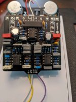
I soldered up an Obsidius the other day and unfortunately something is amiss. I have no signal making its way through the Drive path of the circuit. I've been looking it over and testing with my meter and an audio probe, but so far am coming up empty. I went through the audio path with my probe as suggested by Chuck in a prior thread assisting Vildhjuggah with his Obsidius build. I have signal along the path until I get to IC 4 pin 1. When I work my way backwards through the schematic from IC 4 pin 1, I have good signal from IC 4 pin 7 and can hear it pass through R25. Signal from R25 gets to the front side of R26 and C20, but when I test the output side of those components as well as C21 and IC 4 pins 2 and 3, I lose the signal. I have already replaced R26 and C20 to no avail as well as swapping out IC4 for a fresh chip. Any thoughts or advice would be most appreciated. Voltages and pictures are below.

Thanks again,
Justin

Input Voltage 9.38V

IC1 V
1 4.56
2 4.56
3 2.23
4 0
5 4.56
6 4.56
7 4.56
8 9.11

IC2 V
1 8.33
2 3.2
3 3.16
4 8.34
5 0
6 8.34
7 0
8 0
9 0
10 8.34
11 0
12 8.34
13 0
14 0
15 8.34
16 0

IC3 V
1 4.54
2 4.56
3 2.27
4 0
5 2.23
6 4.56
7 4.56
8 9.11

IC4 V
1 4.56
2 4.56
3 4.27
4 0
5 3.9
6 4.57
7 4.57
8 9.11

Q1 V
D 4.87
S 0.37
G 0

Q2 V
D 9.12
S 4.87
G 3.05

Solder side:
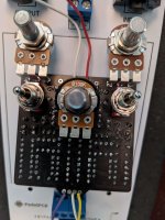
PXL_20210817_184314487 (1).jpg

Component side:
PXL_20210817_184351130 (1).jpg
 
I'd suggest a continuity test between and then I accidently posted. One sec.

*Edit*. Ahem.

I'd suggest a continuity test between c20 and IC4 pins 1 and 2, as well as between R26 and PIN 3. I would try to measure directly on the op amp pin if possible...

It looks like you're using a leaf-type IC socket...there's always a possibility that it may be making poor contact with an IC leg. Maybe try putting *light* pressure on the IC while testing?

It seems to me from what you describe that a few things could be happening. You may have a bad solder joint around IC4, a signal trace could have been damaged around IC4, or the IC socket itself could be causing the issue.

That doesn't mean that one of the three IS absolutely the problem, but it's a place to start.

Hats off, great troubleshooting post. Let's see if we can figure this out.
 
Last edited:
  • Like
Reactions: fig
I'd suggest a continuity test between and then I accidently posted. One sec.

*Edit*. Ahem.

I'd suggest a continuity test between c20 and IC4 pins 1 and 2, as well as between R26 and PIN 3. I would try to measure directly on the op amp pin if possible...

It looks like you're using a leaf-type IC socket...there's always a possibility that it may be making poor contact with an IC leg. Maybe try putting *light* pressure on the IC while testing?

It seems to me from what you describe that a few things could be happening. You may have a bad solder joint around IC4, a signal trace could have been damaged around IC4, or the IC socket itself could be causing the issue.

That doesn't mean that one of the three IS absolutely the problem, but it's a place to start.

Hats off, great troubleshooting post. Let's see if we can figure this out.
Lot of good stuff here. I was wondering about the socket and the traces myself. I'll have to hunker down with the meter and just move through that area piece by piece I think. I'll report back when finished. Thanks again everyone, I appreciate all your help!!
 
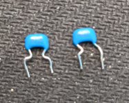
Good news everyone! I checked over the solders with my kid's magnifying glass and touched up a few. Cleaned the board good, still no dice, exact same thing. Continuity check was good, so I plugged the audio probe back in and started my way from the beginning through the entire circuit. Signal was flowing up to the R25 area still. I poked R26, C20, and C21 and somehow heard the faintest of signal from the audio probe coming through that I had not heard before. It barely sounded different from what poking a ground point would. I think the volume on my test rig was a bit louder this time than the last. Anyway...I checked over this area again, measuring resistance and double checking capacitor values. I even whipped out the magnifying glass again and low and behold, one of the little guys below was in C21. It read 105, not 102. I bought those MLCCs from Mouser forever ago and never used them, thought they finally found a home on this project. Couldn't find the baggie they came in, don't know if they were mislabeled, or if I just completely read the tag wrong, but that is less important and will not keep me awake at night. What is more important is that I popped a 1n cap in C2 and C21 and we are now in business!!! I only had one metal film, so the other is a ceramic right now, I'll have to buy another metal film with my next parts order. Glad to have figured this out, thanks everyone for the suggestions and support, I was really starting to pull my hair out on this one. Gotta do some work on the art, then I can drill and box this baby. I can't wait, it sounds great!

A plug here while I am at it, having the Auditorium test board for all my trouble shooting was invaluable. I used to just box things up and pray, I dunno if I would have been able to figure this one out had I had a mess of jacks and switches hanging off the board. I wish I would have had this thing years ago for my builds. I always thought about making a testing rig, but was too lazy. The PCB and parts list made it a no brainer build. Thanks PedalPCB for making my life that much easier!!!

PXL_20210818_195033230.jpg
 
Last edited:
Status
Not open for further replies.
Back
Top