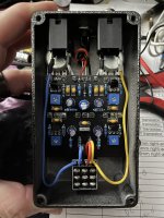
Noise from Cheapo J201? (Umble circuit)

Alright...
I admit I bought a 10-pack of J201s off of Amazon. With the Umble circuit, I'm getting quite a bit of noise when the pedal is engaged. Honestly, could this be due to the quality of (or lack of) the J201s or is the noise just the nature of that higher gain circuit?
Thanks.
 
I haven’t built this one. ROG‘s write-up says there’s some background noise but it’s manageable. Your clip fits my definition of manageable noise in a higher gain circuit fwiw. Could be any of a bunch of things contributing to the noise. I’m not sure it’s the fets tho. Sorry not too helpful.

 
I haven’t built this one. ROG‘s write-up says there’s some background noise but it’s manageable. Your clip fits my definition of manageable noise in a higher gain circuit fwiw. Could be any of a bunch of things contributing to the noise. I’m not sure it’s the fets tho. Sorry not too helpful.

Thanks for your answer. I think I’ll let a couple others chime in, and I agree with you about the “manageable” part. Thanks again.
 
Good looking build!

Did you use shielded cable for the in/out wiring?

How were the wires routed?


In other words — GUTSHOT SVP! 😜
IMG_8185.JPG
This is typically how I wire all my pedals. Still just a paint by number guy, but I've done probably 50+ pedals, and I don't usually run into noise like this. Even the production pedals I've taken the lid off of didn't use shielded wire. Would you suggest that wire for higher gain pedals? How would you utilize shielded wire with the hot coming from the 3PDT and the ground coming from top of PCB?

Thanks for the reply.
 
View attachment 50704
This is typically how I wire all my pedals. Still just a paint by number guy, but I've done probably 50+ pedals, and I don't usually run into noise like this. Even the production pedals I've taken the lid off of didn't use shielded wire. Would you suggest that wire for higher gain pedals? How would you utilize shielded wire with the hot coming from the 3PDT and the ground coming from top of PCB?

Thanks for the reply.
On on your last question, if I understand it correctly – the way I connect my shielded cable is that, with respect to the input/output jack and, I strip the cable and run the inner insulated wire to the tip lug on the jack and run the shielding (twisted and tinned) to the sleeve lug – so the shielded cable basically forms a small Y at the jack (you’ll still run a ground cable from the sleeve lug to the top of the PCB as normal - so you basically have two connections on that sleeve lug – the shield and the ground wire going to the PCB). Since you only need the ground one end, for the end that goes to the 3PDT, you strip the cable, peel back the copper shielding, and run the inner insulated wire to the 3PDT as normal. On this end, you’ll snip off all of the exposed shielding – I usually add heat shrink tubing over the place where the shielding was cut just to make sure that, if there are any tiny bits of shielding still sticking out, it doesn’t inadvertently touch anything else and cause a short.

Mike
 
Is it the common practice to ground the shield at the "signal source" side of the wire run? I've heard that in tube amp construction, and have used that technique when running shielded wires.
 
Back
Top Bottom