Opto-Coupler Tester

Chuck D. Bones

Circuit Wizard
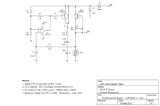
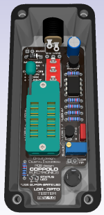
Here is a quick 'n' dirty Opto-Coupler speed tester. It's a relaxation oscillator that uses the LDR's response time to control the oscillator speed. It provides a visual indication of how long it takes for the LDR to get up to 1MΩ after the LED turns off. It can also be used to test LDRs if you cover the LDR & LED1 to keep stray light out. The toggle switch is optional and provides a way to hold the LEDs on or off.
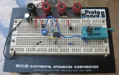

Opto-Coupler Tester 02.jpg

This tester is powered by +18V. U1 senses the voltage across the LDR. When the LDR voltage reaches 10V, U1 turns on Q1 which puts about 2.5mA thru the LEDs. When the LEDs light up, the opto resistance drops quickly and as a result, Q1 turns off. The LDR goes dark, the resistance rises and the cycle repeats. The quicker the resistance rises, the faster LEDs blink. LED1 is the LED inside the opto-coupler, LED2 is a visual indicator. You can vary R6 to adjust the LED current. Q2 is a constant current source that puts 10μA thru the LDR. You can measure the LDR voltage at TP1. Be aware that most DMMs sample the voltage 2 or 3 times per second. Therefore, using a DMM is only practical if you have the toggle switch in either the Center (LDR dark) or Right (LDR lit) position. A fast LDR will blink the LEDs faster than 1Hz. A slow LDR may take several seconds or more to cycle and an LDR with a low dark resistance (<1MΩ) won't cycle at all.
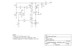
LDR Tester.png
 
Last edited:
This looks like another tester pcb in the pipeline. Might add a charge pump to get the 18V so I can power that from my 9V bench supply.
Would this then be a good way to match optocopler for circuits by testing a few and pairing the ones that have a similar LED freq on test?
Could this be modified for testing LDRs? I guees it would need a "Darkroom" for the LDR to prevent straylight?
"Darkroom" as in some cover that prevents straylight affecting results.
 
No, as long as you pick a value for R6 that gives an LED current around 1 - 2mA. At those currents, you'll want to use a super-brite LED. The LED is only on for a fraction of a second, so you want it to be bright enough that you don't miss it.
 
How's this looking, @Chuck D. Bones:
1695315052623.png
Test point setup as 3.5mm enclosed jack. SPDT is wired to allow adequate room for the ZIF socket and components to be attached without touching the lid. The board should be attached to the enclosure via non-conductive adhesive foam.

If this works out, I'm happy to share the design.
 
Looks great, but I'd prefer to mount the board on standoffs, either free-standing, or on a piece of wood. What do you think of making a version like that with #6 holes in each corner? Also, a square board would be stronger. I realize that totally breaks your design. :(

Trying to operate that ZIF lever will be no fun down inside a box.

Maybe I'll make a Vero. :unsure:
I'll tell you what... If you can help me find a suitable cover that snaps onto the PCB to block light, I'd actually rather design the board to be used outside of a box. I spent way too much time trying to find an alternative (elegant) solution for blocking light and still came up empty.
 
If boxing it up, I'd suggest using leads & grabber clips.
Do you have a link to the leads and clips you're suggesting? I contemplated using banana jacks but space is very limited if the design is set up for 1590A. I'm not against changing the design, hopefully Dave will have some suggestions for PCB covers and I can bring this thing outside of a box altogether.
 
I forgot about the need for a light-tight box. I'll use a bigger box (1590B) so I can get my fingers around the ZIF lever. Two of the mounting screws need to be close to the ZIF socket so as to not overstress the board. I'll install a pair of banana jacks for the meter / scope connection.
 
I forgot about the need for a light-tight box. I'll use a bigger box (1590B) so I can get my fingers around the ZIF lever. Two of the mounting screws need to be close to the ZIF socket so as to not overstress the board. I'll install a pair of banana jacks for the meter / scope connection.
If you're using a ZIF socket and standoffs are a must, I think you're going to have to choose a taller box than 1590A/B. I'm re-working the design for 125B and going to try to accommodate the suggested changes. If you guys have a preferred test point style, feel free to send over a part number so I can pull the datasheet to create a footprint if need be. Kindly remember that to ensure an isolated test environment, the test points should be enclosed and (preferably) panel mounted.
 
Last edited:
I'll use the standard size banana jacks. 5/15" dia hole, 7/16" dia flange, mounted on 1" centers. I'll put the LED and jacks on the side of the enclosure since the bottom is now the top.
 
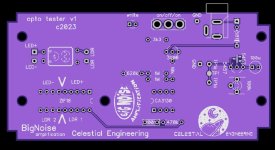
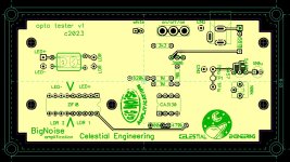
Here's my stab at it.
Should fit into a 125B, holes for standoffs to bolt it down, switch and white LED can be wired into side of enclosure with a bit of ofboard wire.
Whole thing can also be mounted naked outdoors, a few extra pads for spare sockets to mount opto individual or into ZIF socket.
Any good, any tweaks?
opto tester 1.jpg
opto tester 2.jpg
 
Here's my stab at it.
Should fit into a 125B, holes for standoffs to bolt it down, switch and white LED can be wired into side of enclosure with a bit of ofboard wire.
Whole thing can also be mounted naked outdoors, a few extra pads for spare sockets to mount opto individual or into ZIF socket.
Any good, any tweaks?
View attachment 56967
View attachment 56968
Nice board! It looks pretty similar to the revised board I've been working on based on the suggestions that @Chuck D. Bones made above. It looks like your TR1 test point is going to Q2's source instead of drain.
 
Nice board! It looks pretty similar to the revised board I've been working on based on the suggestions that @Chuck D. Bones made above. It looks like your TR1 test point is going to Q2's source instead of drain.
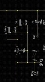
I'm confused now, which is not an unusual state of mind down here. This is the snippet of my schematic I used, do I need to flip the jfet upside down to be correct or what am I missing?
snippet optp tester.jpg
Celestial Engineering has a logo now? Cool!
It's from an earlier UV print design that I did for Chuck, I just plonked it on there because a pcb with that much empty space asks for it and why not. Not sure if Dave wants to keep that logo as final version, he might have a word on that.
 
Back
Top