SOLVED Parenthesis Mini boost no worky

WheatAndBarley

Well-known member

So finally got around to boxing this guy up. I was surprised to find that I get no signal at all when I turn the boost on. The distortion side works and sounds great, and octave is functional though I still have to spend some time matching voltages to get it sounding optimal, but I'm disheartened a bit that the boost isn't working.

I double checked values as well as wiring continuities from the schematic and as far as I can tell I've got all the right things in all the right places. My next two thoughts are that the BS170 I have in there is really old, and also that my switch might just straight up be dead although it passes signal fine and again. the continuities are good so I'm not sure that's the issue. If anyone has any other suggestions I'd love to hear them!
 
Solution
Alrighty, I think I spotted the problem!


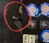
Next to both of the 1uf cap pads there's some exposed copper which seems to be the ground plane. The bit next to the left pad is disconnected from it but there's a tiny bit next to the right pad that is giving me ground continuity so I'm pretty sure thats the culprit. Gonna try to clean up the hole as much as possible and see if I can get it to disconnect.
I see your questioning the switch, have you checked the continuities on the lugs both active and bypass? There can be solder bridges under the breakout board on occasion. You should have continuity between lugs (1,2) (4,5) and (7,8) when active. In bypass you should have continuity between lugs(1,5,6)(2,3)(8,9). The only time you should have continuity horizontally across the break board are pins (1,6) and (3,9) only when in bypass.

Did you have any difficulty when doing the breakout-board? Extended heat?
 
Post good pictures of the solder side. If you have verified component values already, the next step is visual inspection. Does it not work when out of the enclosure too? If nothing comes up from visual inspection, you’re gonna need to get the audio probe out!
Edit: actually, measure transistor and IC voltages first.
 
I see your questioning the switch, have you checked the continuities on the lugs both active and bypass? There can be solder bridges under the breakout board on occasion. You should have continuity between lugs (1,2) (4,5) and (7,8) when active. In bypass you should have continuity between lugs(1,5,6)(2,3)(8,9). The only time you should have continuity horizontally across the break board are pins (1,6) and (3,9) only when in bypass.

Did you have any difficulty when doing the breakout-board? Extended heat?
Turns out continuities on the switches are fine, I was just wondering if I'd finally encountered a dead one after using dozens and dozens of them over the years.
 
Post good pictures of the solder side. If you have verified component values already, the next step is visual inspection. Does it not work when out of the enclosure too? If nothing comes up from visual inspection, you’re gonna need to get the audio probe out!
Edit: actually, measure transistor and IC voltages first.
I'll have to check if it works out of the enclosure tomorrow, it's very possible the boost pot is contacting somewhere it shouldn't be. I was worried that maybe I'd severed the VCC somewhere but I am getting 9.45v on the source and gate and about 0.4v on the drain of the BS170 so I know there's power getting to that section of the circuit.
 
Bingo. You should have around 4.5V on the gate.

Triple check the values and solder joints of R29, R30, and R32.

If that reveals nothing I'd reflow the solder on all three of those and the BS170.

Still no go? Then I'd swap the BS170.
Re-checked, reflowed, swapped to my other two BS170s, tried it outside of the enclosure, still nothing. What are the chances all 3 of my BS170s are bad lol. Are there any common equivalents I might have on hand to try?

Audio probe is next I guess, working through the circuit.
 
Is it possible you got the red and blue measurements mixed up?

Blue should be ground 0V, Red should be near 9V.
Ok whoops, had the one end of the multimeter connected to the wrong point, this changes things a bit.
On the BS170 I have D: 8.96v, G and S both zero.
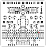
Green: 0v
Red: 8.96v
Blue: 0v

I may have figured out whats wrong however though I still have to figure out why it's happening. I seem to be getting continuity between ground and the G pin of the BS170 as well as everything it's connected to in the schematic, R29/30 and C22.
 
Alrighty, I think I spotted the problem!


Next to both of the 1uf cap pads there's some exposed copper which seems to be the ground plane. The bit next to the left pad is disconnected from it but there's a tiny bit next to the right pad that is giving me ground continuity so I'm pretty sure thats the culprit. Gonna try to clean up the hole as much as possible and see if I can get it to disconnect.
 
Solution
Back
Top