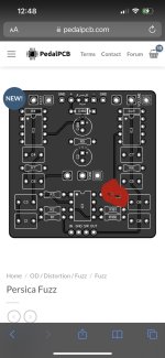
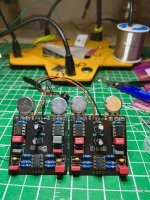
Persica Blues (Frantone peach fuzz) low volume) SOLVED

Svenson007

Active member
Hello out there pedal freaks :)

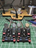
About two years ago I fell in love with Frantone pedals. I’ve built mostly the Cream puff and (I think my favourite Peach Fuzz often on vero board)

I was building the pedal pcb Cream puff’s. I was always hoping for more frantone cuz pedal pcb is my fav. But I could only find a pcb for the Peach fuzz on PCB mania. That’s not idea for me. But it worked well, if a little clunky.

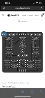
One day it happened. The Persica was posted (peach fuzz) so I ordered a handful of them. Making double pedal plans etc. thing is it is still in the “experimental” stage. Which means no documentation etc. just the components printed on the board. One thing I noticed right away is the Opamp said TL022. So after some research I found out that the TLC2262 (which is in the frantone and pcb mania) should be no problem. All the other components seemed to be the same. The TLC2262 was the default ship for this build… but is it possible the TL022 printed on the board is for a certain reason? I even read you can use a simple tlo72 so I doubt it.

So I built one very carefully. Then I move on to testing. I’ve always just tested using alligator clips to wire, then into the input and output. The other ends to the jacks. Under fresh battery power. Works for me. To my dismay there was very little volume at all. The circuit is powered by two Lm386 chips (along with the TLC adding the character). So I assumed I must have the wrong version of the chip or something. I kept swapping and swapping different 386’s and no volume increase. I have a few pcb’s so started from scratch and the same results. Very low volume.

I just happened to receive an audio injector pen the same day. TC customs makes a sort of all in one audio probe. So I used it to probe my way through the circuit. At some points it would be about as loud as you wound expect… not so much at others. I noticed with R6 (forget the value) it was much louder. The one makes this annoying ambulance sound. It was strong and distorted.

Anyways since there is no docs yet I’m wondering if anyone else has built this pcb and your results. My two are identical besides 386’s for experimenting.

Just sucks as I was so pumped and had been planning, and ordered cases for double frantone / order switcher mode builds.

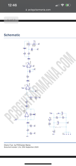
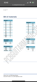
That’s the risk of buying in the no docs state. But I felt I had a pretty firm grip of the circuit. I’ll attach some schematics from other sources etc… and hope we get a pedal pcb version soon. It such a simple pedal I don’t know what could go wrong…. Twice. Some pics will be from pcb mania (components)

Again when I would probe R6 it was pretty loud and distorted. Hooking the other end of the probe I had no problems making my way through the whole build. So no bad components etc.

The board marked TL022 makes me wonder if the pin outs of the IC’s are a problem? The consensus out the is no. But can’t see what else it wound be .

Thanks for listening to my blabbing, I was just really stoked on an idea… so naturally I’m bummed.

Any hints, guesses … anything are welcome!

P.s the last one has its saturation enhanced so colour bands are more visible. I didn’t get a shot of the back because the soldering is sound. And also with my probe my signal makes it from IN to OUT.

Cheers!
 

Attachments

  • F21EB2D2-A4E1-40FC-8C6C-DC8A5D1DE78B.jpeg
    F21EB2D2-A4E1-40FC-8C6C-DC8A5D1DE78B.jpeg
    523.5 KB · Views: 22
  • F5AFDC75-382C-48CA-9754-7A823B0FF101.png
    F5AFDC75-382C-48CA-9754-7A823B0FF101.png
    408.4 KB · Views: 20
  • 7171EA16-3214-485C-9B25-893069334538.png
    7171EA16-3214-485C-9B25-893069334538.png
    282 KB · Views: 17
  • A0123320-19F7-4125-A9E4-0DDD1555BBC2.png
    A0123320-19F7-4125-A9E4-0DDD1555BBC2.png
    295.9 KB · Views: 20
  • 22582E07-1FF5-4BCA-88D2-7B8DA04E0D68.jpeg
    22582E07-1FF5-4BCA-88D2-7B8DA04E0D68.jpeg
    165.3 KB · Views: 24
  • D4FB9EBD-8D4A-4032-B9A9-D826B82AD31F.jpeg
    D4FB9EBD-8D4A-4032-B9A9-D826B82AD31F.jpeg
    572.6 KB · Views: 15
Last edited:
TL022 is what is listed in multiple Rev 5 schematics.

TL022, TL072, and TLC2262 all have the same pinout. There could be some sonic differences between the TL0xx and TLC2262 but I can't think of any reason there would be a massive volume difference.
Where might I find these updated documents? Thanks.
 
They're hard to see in the pic, but are your R7 and R8 the correct values? Also verify the value of C8 is 470n

In another post regarding this, you mentioned pin 8 of Q3 giving you a loud signal :unsure: . You'll be wanting to check for signal at pin 5 for each of the 386s.
Yes R7 and R8 are correct. I ordered some tl022’s just for the off chance that works. Doesn’t sound like it will here though. I’m using tlc2262. I also ordered lm386 N-1.

I remember building an Acapulco good way back and it was specified they had to be lm386 N-1. Possibly this circuit is fussy about thais as well? Dunno why…. But I will try replacing all the chips. I checked over my values a few times now on both boards I built and haven’t found an incorrect value 🤷🏻‍♂️

I’m pretty dang sure I didn’t screwed up to boards of the same circuit in a row.

I just received one of those TC custom electronics signal feeder/receiver pens. I’m impressed with it. I already solved one board out of the pedal graveyard using it.

Also if I touched a screw driver to pin 8 of the lm386 it made it work…. Even though it doesn’t make sense to me…. I have a feeling it doesn’t like my lm386’s

This is funny being stumped by this build after just putting together two MURTON phase 2’s lol 😂

I hope it’s the same thing as the Acapulco gold situation. It was stated it wouldn’t work with anything besides the N-1 version. Right now I have a mixed bag of 308’s after finally burning through my N-1 chips.

Coming from Mouser so I can be confident of that at least.

Yeah this is a strange one. Is your amp maybe running out of clean headroom? On mine, the volume pot at noon is louder than the clean signal, but my amp is set for crystal clear

Another thing you could try if you're not able to get it loud enough with the chip swaps is putting a 10u capacitor across pins 1 & 8 of IC3. That'll bump the gain up from 20 to 200. A resistor in series with that cap will help you fine tune the gain for adequate volume
 
Last edited:
Yes R7 and R8 are correct. I ordered some tl022’s just for the off chance that works. Doesn’t sound like it will here though. I’m using tlc2262. I also ordered lm386 N-1.

I remember building an Acapulco good way back and it was specified they had to be lm386 N-1. Possibly this circuit is fussy about thais as well? Dunno why…. But I will try replacing all the chips. I checked over my values a few times now on both boards I built and haven’t found an incorrect value 🤷🏻‍♂️

I’m pretty dang sure I didn’t screwed up to boards of the same circuit in a row.

I just received one of those TC custom electronics signal feeder/receiver pens. I’m impressed with it. I already solved one board out of the pedal graveyard using it.

Also if I touched a screw driver to pin 8 of the lm386 it made it work…. Even though it doesn’t make sense to me…. I have a feeling it doesn’t like my lm386’s

This is funny being stumped by this build after just putting together two MURTON phase 2’s lol 😂

I hope it’s the same thing as the Acapulco gold situation. It was stated it wouldn’t work with anything besides the N-1 version. Right now I have a mixed bag of 308’s after finally burning through my N-1 chips.

Coming from Mouser so I can be confident of that at least.
Not to be a stickler, but I don’t believe the EQD AG “needs” an LM386-n1. EQD uses the JRC386D, which is equivalent to the LM386-n3 (if I’m not mistaken). Just mentioning in case someone else sees the remark while building their first EQD AG.
 
Not to be a stickler, but I don’t believe the EQD AG “needs” an LM386-n1. EQD uses the JRC386D, which is equivalent to the LM386-n3 (if I’m not mistaken). Just mentioning in case someone else sees the remark while building their first EQD AG.
Sorry for the off-topic, but I also had to add details to this since I just grappled with this issue.

FWIW I built an Acapulco Gold clone, and I'd say that LM386-N1 is the one it doesn't work with. You can also read through the comments here http://tagboardeffects.blogspot.com/2015/11/earthquaker-devices-acapulco-gold.html

Most of them mention the same issues I had with mine (https://forum.pedalpcb.com/threads/aztek-sunn-acapulco-gold-too-much-gain.16890/#post-198733), squealing and a strange cutoff type noise after you stop playing, with buzzy and or fuzzy tone that sounds bad. Most have had better success with N4's or N3's rather than N1's (usually problems seem to be exactly with N1's). LM386L's worked for me - I was under the impression they were the equivalent of N1's from another manufacturer, but they fixed my issues. Apparently some people had more luck with testing the N1's until they found some which worked better than the rest.

At least the first one should not be N1, I switched both to be safe.
Same here. In circuits that use the LM386, I’ve had the least amount of luck with LM386n1’s. Haven’t tried the LM386n4’s yet, but have had consistently positive results with LM386n3’s and JRC386D’s. I wanna say that someone at StompBoxParts (one of my favorite online vendors) told me that the JRC386D’s were the equivalent of LM386n3’s. I could be mistaken, but I think it was when I emailed them because their 386n3’s were out of stock.
 
Ok I swapped to my new chips from Mouser, so you know it’s legit. Same thing. Low volume. I’m super duper bummed. I had some cool plans. I know when I bought a pcb from another supplier they stated it was the V2. Fran advertised it as 2x the gain as the original. So maybe this is the original we have here. Anyone else build it? I’m looking for a comment somebody gave me about attaching certain legs of an IC to get much more volume out of it.

EDIT!!!

You know what I think I might just be crazy. Now when I turn my amp way up through my test rig…..it is defiantly over unity after chip swap…. by a reasonable amount. Not as much power as her V2 which would rip your head off at 9 o’clock. But I think this is a V1 schematic and this is normal. It did not like being tested at low volume. As soon as I gave it some breathing room and turned my AC30 up to around 9 o’clock it sprang to life!! I think I’m ok guys!!
 
Last edited:
They're hard to see in the pic, but are your R7 and R8 the correct values? Also verify the value of C8 is 470n

In another post regarding this, you mentioned pin 8 of Q3 giving you a loud signal :unsure: . You'll be wanting to check for signal at pin 5 for each of the 386s.
Sorry slow reply. But yes they are correct.
 
Ok I swapped to my new chips from Mouser, so you know it’s legit. Same thing. Low volume. I’m super duper bummed. I had some cool plans. I know when I bought a pcb from another supplier they stated it was the V2. Fran advertised it as 2x the gain as the original. So maybe this is the original we have here. Anyone else build it? I’m looking for a comment somebody gave me about attaching certain legs of an IC to get much more volume out of it.

EDIT!!!

You know what I think I might just be crazy. Now when I turn my amp way up through my test rig…..it is defiantly over unity after chip swap…. by a reasonable amount. Not as much power as her V2 which would rip your head off at 9 o’clock. But I think this is a V1 schematic and this is normal. It did not like being tested at low volume. As soon as I gave it some breathing room and turned my AC30 up to around 9 o’clock it sprang to life!! I think I’m ok guys!!

I was wondering about that earlier in the thread. My amps are all set up for sparkling cleans, so I have a ton of headroom.

Glad you've got it sorted!
 
Ok I swapped to my new chips from Mouser, so you know it’s legit. Same thing. Low volume. I’m super duper bummed. I had some cool plans. I know when I bought a pcb from another supplier they stated it was the V2. Fran advertised it as 2x the gain as the original. So maybe this is the original we have here. Anyone else build it? I’m looking for a comment somebody gave me about attaching certain legs of an IC to get much more volume out of it.

EDIT!!!

You know what I think I might just be crazy. Now when I turn my amp way up through my test rig…..it is defiantly over unity after chip swap…. by a reasonable amount. Not as much power as her V2 which would rip your head off at 9 o’clock. But I think this is a V1 schematic and this is normal. It did not like being tested at low volume. As soon as I gave it some breathing room and turned my AC30 up to around 9 o’clock it sprang to life!! I think I’m ok guys!!
You’re not crazy, I had the same experience with a couple other pedals I’ve built. I’d test them out at 8:00pm with my amp at bedroom levels (or perhaps even lower, at the wife’s in bed levels) and I wasn’t impressed at all. The next day, I’d give it a shot at a decent time with the amp cranked and it sounded pretty damn good. Seems like some just want to be ran through some decent output. Glad you got it sorted!
 
You’re not crazy, I had the same experience with a couple other pedals I’ve built. I’d test them out at 8:00pm with my amp at bedroom levels (or perhaps even lower, at the wife’s in bed levels) and I wasn’t impressed at all. The next day, I’d give it a shot at a decent time with the amp cranked and it sounded pretty damn good. Seems like some just want to be ran through some decent output. Glad you got it sorted!
Thanks! And I’m glad I’m not the only crazy one. I’m now on peach fuzz #4. All is well.
 
You’re not crazy, I had the same experience with a couple other pedals I’ve built. I’d test them out at 8:00pm with my amp at bedroom levels (or perhaps even lower, at the wife’s in bed levels) and I wasn’t impressed at all. The next day, I’d give it a shot at a decent time with the amp cranked and it sounded pretty damn good. Seems like some just want to be ran through some decent output. Glad you got it sorted!
I mostly just use the Quad Cortex and headphones so actual volume is pretty meaningless - but I like to run my pedals into a slightly dirty amp. In one sense it's "cheating" since you're combining the pedal with the overdriving modelled tubes, but to be honest I think at very low and clean volumes a lot of pedals don't actually sound that amazing. It's that combination of the pedal's own clipping mixed in with a little bit of amp breakup that is magical IMO.
 
Back
Top