I've used those wires before. They work, but are too long for my taste when hooking up to the protoboard pins. I now use ones from Tayda with really no problems. They're cheap and come in a big pack, so if one breaks once in a while, no big deal.
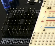
Also, those "extra" pins on the side are for convenience. For example, you may want 2 rails to be 9V, one rail to be 18V, and a third rail to be -9V. Those extra pins there make is possible without jumpers stretching vertically across breadboards.