Question about Breakout boards

Crash102

Well-known member
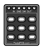
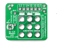
I feel like these are simple questions, but I either my google skills are lacking or the I don't know enough to type what i need to type to find the answers. I had a few of these 3pdt breakout boards from Love my switches. I think they're probably not the same orientation at the ones Pedal PCB sells. I just built a Seabed delay and it works. However, when engaged, the led is off, and when off, the led is on. And my best guess is the breakout board. I'm comparing them, and see that the G is in a different spot, but the love my switches board has a V+ and the Pedal PCB board has a SW. After searching the internet and finding nothing, I Figured, why not try to switch them. but that doesn't work. I figured I'd try here, before I start de-soldering.

Also, I know that the 3pdt switch can be oriented horizontally. But is there a front or back to them?
 

Attachments

  • 3PDT.jpg
    3PDT.jpg
    119.9 KB · Views: 1
  • image_2021-12-16_123032.png
    image_2021-12-16_123032.png
    885 KB · Views: 1
The breakout boards should be installed such that the solder lugs are parallel with the op of the board (like this: — ) and the silkscreen is facing up like in the pictures you posted. As long as the lugs are oriented correctly, flipping the 3PDT 180º is electrically the same. To use the LMS breakout board with a PedalPCB project, you are right that you will have to switch some wires. "SW" on the PPCB board is similar as "V+" on the LMS board. Since the LMS board lets you install an LED to the breakout, that pad is tied to V+. With the PPCB board, the SW connects to the cathode of the LED on the project board and connects it to ground when the effect is active.

When you tried switching the wires from the project board to the LMS breakout, what happened? Also, where are you installing your LED?

If you already have a CLR installed on the main effect board (this is the case with PPCB projects), you don't need the CLR on the LMS board. The LMS breakout has the CLR wired between the cathode of the LED and ground. You'll also have to place a jumper between the LED pads on the main PPCB project board.
  • If you want to install the LED on the LMS board and have the CLR installed on the project board, you'll have to bypass the LMS CLR either by installing a jumper in the CLR spot OR follow the "Prewired LED" instructions to install the LED.
  • If you want to install the LED on the PPCB project board, you'll have to make it so that the LED anode pad is jumped to the top CLR pad on the LMS breakout board (see the photo below).
LMS Breakout Board for PPCB projects..png
 
Last edited:
I ran into the exact same problem on a recent build. Just get a jumper wire, put 9v to the pedal and start touching the jumper from where you have the LED + currently to various places at that circuit and see if you can get the LED to comply. (I think I did end up removing the LED+ and put it on the LED BLK pad, but I don't remember now.) Usually, whether you use those breakout boards from Lovemy... or GGG, or whoever, they have a circuit trace printed on both sides somewhere well enough that you can chase down where the signal is going. The jumper wires are just a quick way to do that.

These PCB boards are all pretty much standard and basically this is your guy, circled in yellow. You have to make sure he's going to a place where the signal is interrupted when he's not in use. As I look at the Love breakout board, it would appear the trace goes to the "BLK" pad at the end of the dropping resistor marked CLR, but YMMV.

Inkedswitch_LI.jpg
 
Last edited:
The breakout boards should be installed such that the solder lugs are parallel with the op of the board (like this: — ) and the silkscreen is facing up like in the pictures you posted. As long as the lugs are oriented correctly, flipping the 3PDT 180º is electrically the same. To use the LMS breakout board with a PedalPCB project, you are right that you will have to switch some wires. "SW" on the PPCB board is similar as "V+" on the LMS board. Since the LMS board lets you install an LED to the breakout, that pad is tied to V+. With the PPCB board, the SW connects to the cathode of the LED on the project board and connects it to ground when the effect is active.

When you tried switching the wires from the project board to the LMS breakout, what happened? Also, where are you installing your LED?

If you already have a CLR installed on the main effect board (this is the case with PPCB projects), you don't need the CLR on the LMS board. The LMS breakout has the CLR wired between the cathode of the LED and ground. You'll also have to place a jumper between the LED pads on the main PPCB project board.
  • If you want to install the LED on the LMS board and have the CLR installed on the project board, you'll have to bypass the LMS CLR either by installing a jumper in the CLR spot OR follow the "Prewired LED" instructions to install the LED.
  • If you want to install the LED on the PPCB project board, you'll have to make it so that the LED anode pad is jumped to the top CLR pad on the LMS breakout board (see the photo belot

Thanks so much. Got it working.
 
Back
Top