Rangefinder: Weak, crackling sound when turned on

thefooldog

New member
Hi everyone! I started my first PedalPCB projects over the winter and had some successful builds with a few boost and drive circuits.

Surprisingly, I couldn't get my Rangefinder build to work properly.

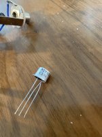
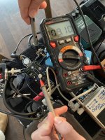
Bypass works fine, LED turns on fine, but I get a thin-sounding, crackly version of the dry signal instead of any kind of boost. I'm using some Polish AY33S transistors that I believed were a feasible replacement for AC128, but I suppose those could be part of the problem. To try to rule out the transistor, I socketed and tested with a few different units from the batch of 20 that I bought, and I even tried reorienting the legs in case the pinout was not what I thought.

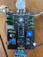
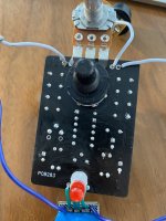
Here are some photos, the board is in pretty rough shape at this point after having replaced some components and reflowed the solder joints several times.

Any help would be appreciated, thanks!
 

Attachments

  • IMG_0143.jpg
    IMG_0143.jpg
    1.3 MB · Views: 28
  • IMG_0144.jpg
    IMG_0144.jpg
    1.6 MB · Views: 27
  • IMG_0146.jpg
    IMG_0146.jpg
    1.3 MB · Views: 27
With the bias trim pot? I just tried twisting it through its whole range and it didn't seem to affect the problem. Thanks!
Your 'crackle' description tells me that your issue is transistor bias. Do you have a multimeter? In order to properly bias a fuzz circuit you need to set the trim pot so that the collector measures around 4.5v. Also, do you have any idea of the hfe of the transistors?
 
Hmmm, I just tried to measure with my multimeter and didn't get a result that made much sense...-9.1v? Turning the bias pot actually had no effect.

How did you measure? Positive lead goes on the collector of the transistor. Negative lead goes to a ground point.
 
Yes, positive (red) lead on the collector (opposite of the transistor can 'tab' side leg), negative lead (black) on the ground. I'm doing this without the pedal in its case so I'm using the shield of the output jack as the ground point for the negative lead—does that check out?
 
That ground point should work. I usually use that point, or the negative of the power Jack. Thinking about it a bit, I believe the bias for a Rangemaster is supposed to be around -7v, not the -4.5v I mentioned earlier. Try turning the trim pot all the way to the left, and measuring again.
 
Interestingly, it's still the same with the trim pot fully counterclockwise, -9.1v. Here's a photo in case that reveals anything that I'm getting wrong still.
 

Attachments

  • IMG_0147.jpg
    IMG_0147.jpg
    1.8 MB · Views: 8
Hmmm, it's a 3-pin 3362-style trim pot which seems to have only one possible orientation on the PCB.

Here's a quick video I took showing what happens as I adjust the position:


Is it possible the trim pot is faulty? I could try replacing it.
 
Hmmm, it's a 3-pin 3362-style trim pot which seems to have only one possible orientation on the PCB.

Here's a quick video I took showing what happens as I adjust the position:


Is it possible the trim pot is faulty? I could try replacing it.

You have a faulty connection somewhere in the bias string.

Check you base resistors, collector resistor (boost pot) and emitter resistors and reflow this joints.

If you have source voltage on the collector, the transistor is not forward biasing for some reason.
 
Hmmm, it's a 3-pin 3362-style trim pot which seems to have only one possible orientation on the PCB.

Here's a quick video I took showing what happens as I adjust the position:


Is it possible the trim pot is faulty? I could try replacing it.
What does the Trimmer have written on the Side of it ie 501, 502
Do your Transistor legs match Letters I have put on the PCB Board????
Rangefinder CBE.jpg
 
You have a faulty connection somewhere in the bias string.

Check you base resistors, collector resistor (boost pot) and emitter resistors and reflow this joints.
Looking at the schematic that's R2 and R3, I suppose? I feel a bit lucky this is such a simple circuit. I'll measure their resistance quickly to see if it's as I'd expect.

What does the Trimmer have written on the Side of it ie 501, 502
P502
T020
Do your Transistor legs match Letters I have put on the PCB Board????
I suppose I can't be 100% sure because I haven't found a datasheet for the AY33S, but the housing appears to be TO-18-style in which case it would be correct.
 
Back
Top