Caldo71
Active member
Okay this might sound like dummy talk because I don't know the proper terminology so bear with me...
So you guys know how all of the PCBs that are sold by pedalpcb.com use the typical old-school 1/4" mono jacks for inputs/outputs that require only two leads—"positive" and "ground", right?
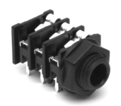
Well I have this other PCB-based project (it's not a stomp box it's an effects looper) that uses those much more "fancy" 1/4" mono jacks that have not two, but SIX contact pins going into the PCB...this kinda situation...


...but I don't WANT to use those fancy jacks! In truth I'm hoping to "hard wire" the ins/outs on the stomp box PCBs DIRECTLY to the in/out PCBs of the looper kit. Because it's not really gonna be a looper with external jacks on a floorboard connected to a bunch of freestanding pedals or any of that nonsense...this is all gonna be housed internally in a rack-mountable enclosure.
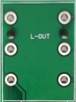
So this is probably really basic shit that I should know, but can someone here possibly do some scribbles on that second image (the PCB) to tell me which of those six pads are the "+" and the "ground" and if I need to jumper any of the other pads to bypass the whole open/closed circuit thing that those fancy jacks are intended for?
Thanks in advance.
So you guys know how all of the PCBs that are sold by pedalpcb.com use the typical old-school 1/4" mono jacks for inputs/outputs that require only two leads—"positive" and "ground", right?
Well I have this other PCB-based project (it's not a stomp box it's an effects looper) that uses those much more "fancy" 1/4" mono jacks that have not two, but SIX contact pins going into the PCB...this kinda situation...


...but I don't WANT to use those fancy jacks! In truth I'm hoping to "hard wire" the ins/outs on the stomp box PCBs DIRECTLY to the in/out PCBs of the looper kit. Because it's not really gonna be a looper with external jacks on a floorboard connected to a bunch of freestanding pedals or any of that nonsense...this is all gonna be housed internally in a rack-mountable enclosure.
So this is probably really basic shit that I should know, but can someone here possibly do some scribbles on that second image (the PCB) to tell me which of those six pads are the "+" and the "ground" and if I need to jumper any of the other pads to bypass the whole open/closed circuit thing that those fancy jacks are intended for?
Thanks in advance.

