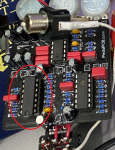
Sea Horse Troubleshooting

neil463

New member
If voltage measurements are required, please let me know. I'm doing some initial troubleshooting and figured I'd ask for guidance.

The pedal is not completely working when engaged. If all knobs are maxed there is a slapback like affect, but the LED is not on or blinking. While turning the Rate knob I did notice that the LED briefly came on, but wasn't able to repeat this.

It seems like the Dimension, intensity, Animate, and Depth knobs all have some level of functionality where as Shape and Rate do not. Am I correct in thinking I need to be looking at the section of items that are connected to the LM324? Any further direction would be fantastic.
 
Sounds like the PT3299 is working.
There are two versions of the Sea Horse board, which one do you have?
Did you follow the BOM exactly, no parts substitutions?
Did you clean and inspect your board after soldering?
Have you rechecked all of the component values?

Please post clear hires pictures. We have to be able to check the components and solder joints.

Once we get your board up and running, we can talk about getting rid of the dreaded LFO tick.
 
Thanks for the reply - I appreciate it. At some point in the next day or two I plan to get my DMM and check out voltages on the ICs

Not positive on the version - I bought it Jan 10th, 2020, so i believe it was the last batch BEFORE the latest revision

No part substitutions. Somehow overlookedt his one. Didn't have a 470 ohm 1/8 w resistor, so used 470 ohm 1/4 w. Doesn'ts eem like that would be applicable here but LMK.

I inspected but have not cleaned - i've read conflicting information on what to use to clean the board so i didn't. I used Kester 24-6337-8800 No clean solder if that helps.

My solder joints look pretty good for me, I reflowed around the rate pot because, as mentioned, I noticed the LED lit up when i was using it once.

I was hoping to narrow the search down before checking all component values, that said I'm pretty confident I used the correct values as I worked one value at a time based on the silk screening on the device.

Uploaded images to IMGUR -
 
Last edited:
If the LED is not flashing then the LFO is not working. Your board looks pretty good from what I can see. I flood my boards with 90% IPA and scrub with a toothbrush. It's ok if clean IPA gets into the sockets and pots, but you don't want dirty IPA getting in there, so use gravity to your advantage.
You have the latest rev of the board. The only change from v2 to v2a is the naming of the INTENSITY and DEPTH pots.

IC4 is the LFO, so check the voltages on that and verify the component values around it. When the LFO is working, IC4-1 will switch back and forth between 1V and 8V. IC4-14 will ramp up & down. With SHAPE set to zero, pins 7 and 8 will ramp up & down.
Thanks, will do. Looks like I either have C7 or C15 + C17 put in backwards. I'm thinking it's C7.
 
Looks like a couple of your electro caps are installed backward (c15,16)

Hmm I don't think I did, but your reply led me to double check. I think maybe I Have C7 backwards. See this pick - the BP side is the short lead


And then int his pic you can see C7 & C15+C16 all facing the same way, with BP side (negative) pointing "down"


That's frustrating - i have to remove a pot to get at that... Thanks for making me zone in!
 
If the LED is not flashing then the LFO is not working. Your board looks pretty good from what I can see. I flood my boards with 90% IPA and scrub with a toothbrush. It's ok if clean IPA gets into the sockets and pots, but you don't want dirty IPA getting in there, so use gravity to your advantage.
You have the latest rev of the board. The only change from v2 to v2a is the naming of the INTENSITY and DEPTH pots.

IC4 is the LFO, so check the voltages on that and verify the component values around it. When the LFO is working, IC4-1 will switch back and forth between 1V and 8V. IC4-14 will ramp up & down. With SHAPE set to zero, pins 7 and 8 will ramp up & down.

Going to validate values next, here are the voltages with Shape @ 0, everything else up to max. Voltages were stable.

  1. 0
  2. .5
  3. .33
  4. 1.05
  5. .566
  6. .100
  7. .100
  8. .56
  9. .56
  10. .52
  11. 0
  12. .52
  13. .58
  14. .57
 
The only pin that has the correct voltage on it is pin 4 (GND). Pin 4 is Vcc, should be +9V. If that's not there, then nothing else will be right.
Check pin 4 on IC1, should be +9V. We may have a power problem.
Where are you grounding your meter?

Regarding C15 & C16, what do you mean by BP side?
 
The only pin that has the correct voltage on it is pin 4 (GND). Pin 4 is Vcc, should be +9V. If that's not there, then nothing else will be right.
Check pin 4 on IC1, should be +9V. We may have a power problem.
Where are you grounding your meter?

Regarding C15 & C16, what do you mean by BP side?


Pin 4 on IC1 is also ~1V

Grounding on the - terminal of the DC jack (alternatively, also grounded on the ground of the output jack

Sorry, the caps have markings. THe short lead side has BP written on it where I'd normally expect a negative or Gray stripe.
 
Let's check the power in a couple other places:
D2 anode and cathode.
IC3 pin 3.
Looks like a cold solder joint where the output jack's ground lead is soldered to the board.
D2 1.1 and 1.46

IC3

Which is pin 3? one of them I have 1.1 and the other I have ~.05

Reflowed the solder on that as well as where ground hits the board. There was a long lead that needed trimming, so i took care of that. Validated continuity between ground @ dc jack, ground @ board, ground to input and output, grnd on board the 3pdt side, and GRND on the 3pdt.
 
Last edited:
If the flat side is facing you, pin 3 is on the right.
Looks like there isn't +9V anywhere on the board. Check the power right at the power jack. Make sure the connections from the power jack to the board are good.
Post a pic of your meter.
 
If the flat side is facing you, pin 3 is on the right.
Looks like there isn't +9V anywhere on the board. Check the power right at the power jack. Make sure the connections from the power jack to the board are good.
Post a pic of your meter.

First off, thanks for taking the time to answer my questions and help me out.

I am seeing that the measurement even at the jack is low. Also looks like i did a crappy job of soldering on the jack. I suppose I could just dump it and use a dif't one. Swapping in a 9v batterry seems to prove that out as the light seemed to start blinking at least. The TL074 gets screaming hot (so hot i can smell it and it burnt my finger) and it still didn't seem to actually be working. The 9v also got warm.


Images here:
 
Last edited:
You're welcome. Helping each other out is what we do here.

Is IC3 warm to the touch?

Power off, pull out the ICs, power up and measure the voltage at the jack again. Either there is a short, or something like it, on the board or your power supply is fubar.

I see the hot pink Tayda box in the background. Gonna be a great looking pedal when you're done with it.
 
IC3 is not warm to the touch. I clipped off the power jack and had clipped a 9v to the power leads using alligator clips, and still had IC1 get hot as hell. There's also no sound when engaged, which normally i'd chalk up to a wiring issue, however prior to this it did pass sound when engaged.

I'll do some more checks later today.
 
Back
Top