Shika Fuzz build on the Muffin Fuzz Board

I built one of these. I can confirm it is a Big Muff

I still don't know what the change in tone pot to 50K does. In fact, do we know why all the pots are 50K?
 
I built one of these. I can confirm it is a Big Muff

I still don't know what the change in tone pot to 50K does. In fact, do we know why all the pots are 50K?
Yep, from what I've seen, interviews and such, it's a Chinese knock-off of a big muff, the elf muff, or fuzz or something.
 
Yep, from what I've seen, interviews and such, it's a Chinese knock-off of a big muff, the elf muff, or fuzz or something.

Elk Big Muff/Super Fuzz Sustainar, by Gakki (Japan). It was a clone of a 1972 Triangle BMP, which had a reversed tone control, and a much smaller cap (330p). Using that value, the fuzz is kinda rough. Luckily the components drifted over time, and the pedals matured into a much better sounding fuzz…
 
I’d like to address the other elkephant in the room…
The original Gakki was PNP silicon.

I was expecting the Shika to have a built-in charge pump to get the negative-ground to run PNP off a regular power supply.

I don’t see the reason to offer a different PCB if I can build this on the Muffin with added charge-pump and offboard wiring the tone pot in reverse… 😸
 
I asked Mr. PedalPCB the same question a long time ago and the answer is that although some of us are smart enough to build different pedals on the same board by making our own BOM and so on, not everyone who buys boards here has that capability.

An upside-down version of the Muffin board would be fun because then we could build a PNP BMP without a rotten old charge pump.

The first pedal I ever traced was a PNP Triangle Muff. Since it ran on batteries, polarity was not an issue. There is are two or three related errors on this schematic. Who can spot them?

Big Muff Triangle circuit trace [1975].png

Here's a weird piece of space trivia...
At the time, my Dad was an engineer on the Viking Lander Biology Instrument (google it). He would bring home stacks of old printouts which I would use for scratch paper. This particular page was from a test report. If you flip the picture vertically, the header reads: "...PROCEDURE FOR BIOLOGY SEQUENCE..."
 
Last edited:
I’d like to address the other elkephant in the room…
The original Gakki was PNP silicon.

I was expecting the Shika to have a built-in charge pump to get the negative-ground to run PNP off a regular power supply.

I don’t see the reason to offer a different PCB if I can build this on the Muffin with added charge-pump and offboard wiring the tone pot in reverse… 😸

I built an Elk BMS (with an ‘a’) a few months ago on a Muffin board. I started with the 330p schematic value. I then added another (660p now). Sounds better. I’m toying with the idea of swapping in the 3.4n (or whatever it is). I haven’t yet, though.

The aforementioned build also includes a toggle for the Triangle circuit the Elk was copied from (but with a reversed tone control). It’s a very extreme circuit. Lots of bass, lots of treble, very smooth…
 
I asked Mr. PedalPCB the same question a long time ago and the answer is that although some of us are smart enough to build different pedals on the same board by making our own BOM and so on, not everyone who buys boards here has that capability.

An upside-down version of the Muffin board would be fun because then we could build a PNP BMP without a rotten old charge pump.

The first pedal I ever traced was a PNP Triangle Muff. Since it ran on batteries, polarity was not an issue. There is are two or three related errors on this schematic. Who can spot them?

View attachment 22605

Here's a weird piece of space trivia...
At the time, my Dad was an engineer on the Viking Lander Biology Instrument (google it). He would bring home stacks of old printouts which I would use for scratch paper. This particular page was from a test report. If you flip the picture vertically, the header reads: "...PROCEDURE FOR BIOLOGY SEQUENCE..."
Q3 diodes appear to be going in one direction? I'm also scratching my head with the tone control. It's hard reading these standing on my head. Those damn PNPs!
 
You have Emitters tied to ground?

Oh, that's not a switch...hmm

I give up...
1. The resistor from the top of the TONE pot to ground is missing.
2. The rotation of the TONE pot is shown backwards.
3. The TONE pot resistance is actually 100K. I must have measured it in-circuit and you know what happens then...

I was probably definitely stoned when I traced that pedal. :cool:

That BMP board had a positive ground. It's simple to reverse the polarities when the power comes from an internal battery.

The old BMPs were not true-bypass because they used SPDT stomp switches and the board input was always connected to the input jack. It was like the Flintstones back then.
 
OK, I suspected as much, but wasn't 100% sure. Thanks for clarifying.

I build all my Muff circuits in octagon Hammond enclosures. There is so much empty space that I like to pop a toggle in for something: Green Russian/Civil War, The 73/Violet, ‘73 Ram’s Head/mid-boost. I’m planning a ‘77 V3/Zappa mods build next…
 
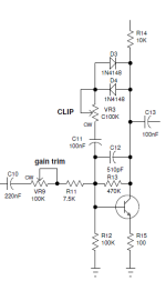
When I saw the Zappa mod on Kitrae's page, I put a 100K trimpot in series with the Muffin's R12 on the BMP I was building. It really smooths things out, if that's what you want. 50K trimpot is probably plenty, but I didn't know at the time. Ignore the ref des in the pic below, they do not match the Muffin Fuzz.
BMP gain trim.png
 
When I saw the Zappa mod on Kitrae's page, I put a 100K trimpot in series with the Muffin's R12 on the BMP I was building. It really smooths things out, if that's what you want. 50K trimpot is probably plenty, but I didn't know at the time. Ignore the ref des in the pic below, they do not match the Muffin Fuzz.
View attachment 22609

That’s an interesting idea. I may try that out.
 
Back
Top