SOLVED: Diptrace noob. Help, please....

BuddytheReow

Breadboard Baker
I finally bit the bullet and downloaded diptrace. I'm trying to get my feet wet and build a LPB-1 schematic and convert it to pcb. I found a simple 2n5088 bjt, but im completely lost where to find anything else in the library. Can someone point me in the right direction? I have no idea wtf I'm doing....
 
The first thing I worked on in DipTrace was renaming and/or creating the components I needed.

Things go faster when you aren’t using a codex to try and decipher WTF the names in the DipTrace or even Rullywow libraries are.

With that said, start with the Rullywow library. I’ve definitely created TONS of my own patterns and components but Rullywow should be what you need to get started and not pull out all your hair.
 
OK. I downloaded the rullywow library and took a shot at making a simple electra distortion. The schematic is ok, but when converting to pcb its a mess. Am I using the wrong jacks or power?
 

Attachments

  • electra.pdf
    6.4 KB · Views: 26
Not on Diptrace but i would say the symbols for the schem are not as important as the footprint for the components. Again not sure how Diptrace works just a thought.
 
Have you set a foot print for each component type?

For the resistors are you using the standard 1/4w footprint?

For the Caps they all have different sizes and footprints pay attention to those. This goes for all the following components.

What exactly is happening when you try to convert to the PCB design?

If youre missing components thats a sure sign your program is not picking up the footprints you assigned.

I would recommend also downloading the MadBean Library. He has all the footprints you need.
 
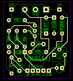
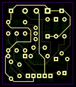
Alright. Here's my first go around at an electra distortion. It's small enough to fit in a 1590a I think. Can someone give this a sanity check? Do I need to add a ground plane? Comments/suggestions are encouraged. I've never done this before. I used the rullywow library and don't know how to remove the pad names (U1, U2, etc.)

1681866838248.png

1681866881934.png
 
Ground plans are good and can eliminate a whole bunch of extra manual routing. Right angles are "bad", but it's honestly more of a cosmetic problem. There are a number of traces that could take more direct routes between the components. Go in one direction as far as you can, then turn rather than having jogs in middle. Use the verification menu to apply some sanity checks to your layout, especially if you add a ground plane. It'll help you find places where it might be broken. You don't need to always follow the rat lines. If multiple components share the same net you can connect them in any order, which might simplify your routing a bit. I'm also a total rookie as far as this stuff is concerned, but those are a few suggestions.
 
Back
Top