Spatialist reverb issue

jrh312

Member
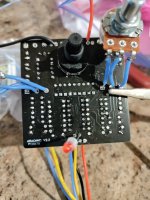
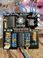
I put together the Spatialist (FV1 soldered on by PedalPCB) but am having issues. More doesn't work than does work.

1. Volume pot is functioning backwards....full left is max volume.

2. Mix pot acts as volume also, so I m assuming "max volume" on the mix pot is actually a full dry signal and "no volume" is full wet.

3. Top 3 pots do nothing at all.

4. Rotary switch causes no change, but I can hear a dull thud when I switch it. Causes no change to the sound and all sound just like it's bypassed.

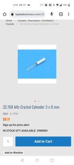
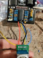
I also included a screenshot of the oscillating crystal I'm using because I had some on hand. It's the same frequency as the one in the BOM but I got it from Tayda so it might not be an exact match. Wondering if that might be the issue because it seems like the FV1 is not functioning as it should.
 

Attachments

  • IMG_20230217_170828.jpg
    IMG_20230217_170828.jpg
    395 KB · Views: 49
  • Screenshot_20230216-204014.jpg
    Screenshot_20230216-204014.jpg
    103.5 KB · Views: 47
  • Screenshot_20230217-054528~2.jpg
    Screenshot_20230217-054528~2.jpg
    105.4 KB · Views: 36
  • Screenshot_20230217-054722.jpg
    Screenshot_20230217-054722.jpg
    221.5 KB · Views: 50
  • IMG_20230217_170648.jpg
    IMG_20230217_170648.jpg
    471.2 KB · Views: 53
  • IMG_20230217_170729.jpg
    IMG_20230217_170729.jpg
    437.3 KB · Views: 51
Have you been able to check components and reflow solder. Do you have an audio probe. If you don’t a quick google search should solve that problem cause they’re easy enough to make. It does sound like the issue is in your wet signal.

Have you checked the voltages?
 
Have you been able to check components and reflow solder. Do you have an audio probe. If you don’t a quick google search should solve that problem cause they’re easy enough to make. It does sound like the issue is in your wet signal.

Have you checked the voltages?
I've rechecked the easy stuff but haven't gone into things like resistors and caps yet, aside from checking polarity of the electrolytics.

I have built a probe on another pedal project but I've never been able to successfully use it, so I'm not confident in it at all. I'd imagine I'm going to have to make a run at it though.

I have checked some voltages, but I'm not sure what I'm looking for aside from what I've found in some other threads. I know enough to find that the center pin on the rotary and one leg on the smallest IC is a 3.3v but other than that I have no idea what's an expected voltage anywhere else really.
 
It sounds like you might've wired your VOL and MIX pots backwards.

EDIT: You might also want to reflow some of those joints. There could be a possible cold joint.
 
What’s your footswitch board? Where’s it from
And is it the same as PPCB’s? Is it backwards? Usually the switch would be facing the other way when mounted in an enclosure.

Here’s mine for a comparison:

53913728-B151-4F5C-95AD-5C2026B98261.jpeg
 
What’s your footswitch board? Where’s it from
And is it the same as PPCB’s? Is it backwards? Usually the switch would be facing the other way when mounted in an enclosure.
Stompboxparts board. I believe it's in right, but that may not be the case. All I can tell you for sure is that the LED is off in bypass but comes on when engaged, for whatever little that may be worth.

For future reference, how would you know which way to put one on if it doesn't say "text up" or something to that effect?
 
Going to do that now. Would the rotary voltages depend on where the switch was in it's rotation? Is there a best way to measure those?
Check the center pin of rotary switch and the rotation shouldnt affect voltages.


Check the TL074
Check pin 8 on IC2
Check pins 6 and 23 on FV1.
 
Stompboxparts board. I believe it's in right, but that may not be the case. All I can tell you for sure is that the LED is off in bypass but comes on when engaged, for whatever little that may be worth.

For future reference, how would you know which way to put one on if it doesn't say "text up" or something to that effect?

Check the traces and make sure they follow this:

CDE111F1-B7B4-44B2-A716-5770790D08E0.jpeg

If you can’t tell, then just wire it up without the breakout board.
 
Are your V in and V out for your voltage regulator backwards?

Your V in should be getting close to 9V and V out should be 3.3V
I was basing the orientation off of this diagram, so if the diagram is correct then what I had listed is right. Just double checked it again.
 

Attachments

  • L78-L333-ACZTR-005.jpg
    L78-L333-ACZTR-005.jpg
    12.4 KB · Views: 2
Back
Top Bottom