szukalski
Well-known member
This took a while but I finally got there..
I decided to make myself a Lightspeed, but wanted to have a little extra gain for moments when that mood arises, so I made a PCB with switchable gain following this tip by Chuck. That board (v1) had oscillation. Learning curve I said, bad PCB design. So I made another (v1.1). Same oscillation. A less lazy troubleshooting found that I had connected my gain feedback loop to ground instead of Vref (foolish sheep). I hacked up the board and it worked as expected. A Lightspeed with a smidge more gain on a DPDT switch.
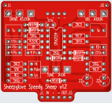
I was also working on a dual relay board and wanted it to control the gain switching, but the existing board was 4-knob layout, and I wanted 3-knob so I made a third revision of the board. At the same time, I had worked out the kinks (naughty sheep) from the dual relay board and it all came together as you see below.
Sound wise, it's a Lightspeed. You know it. Boost your amp and enjoy as you would with a Timmy. Wait? You want a smidge more gain.. hold down the soft relay footswitch and you'll change the channel.. cool stuff.
About the dual relay board. It's using an ATtiny85 with one footswitch, two relays, and two LEDs. Channel 1 is the signal path, channel 2 is the set of DPDT pads on the left. In the configuration below, I am using a bi-colour LED, turn on and off for channel 1, change colour based on channel (green for 1, red for 2). The channel persists when you bypass the pedal (not on power-off, but it can be easily implemented).
One thing about running two channels from a single footswitch, you need to decide what to do when you lift the footswitch because you need to decide whether it has been held down for a time to change channels or just a momentary to bypass. This means that it feels a little different than a normal relay bypass which takes effect immediately. A different approach would be to use double-tap to change channels (leaving hold for momentary toggle of channel 1). Watch this space..
Pics.. no faceplate for this one. I'm doing a Michael. Last of my Tayda enclosures, I use Daier gloss black these days.

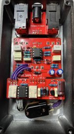
The guts. If the relay looks a bit messy.. did I mention that I accidently built an earlier revision by mistake and had to desolder everything and built the correct one? (Meek sheep). I use one side of the channel 2 DPDT for the gain toggle (it should be under the board, but muggins here got the gain channel labels wrong. Silly sheep). The other side of the DPDT is for the bi-colour LED. If you want to use both sides of the DPDT for the pedal, then there are LEDs per channel.
A couple of things which I have found really useful in my own design philosophy.

This was more a proof-of-concept design than anything else, I still work on the dual relay to improve functionality but as-is, it works well.
I decided to make myself a Lightspeed, but wanted to have a little extra gain for moments when that mood arises, so I made a PCB with switchable gain following this tip by Chuck. That board (v1) had oscillation. Learning curve I said, bad PCB design. So I made another (v1.1). Same oscillation. A less lazy troubleshooting found that I had connected my gain feedback loop to ground instead of Vref (foolish sheep). I hacked up the board and it worked as expected. A Lightspeed with a smidge more gain on a DPDT switch.
I was also working on a dual relay board and wanted it to control the gain switching, but the existing board was 4-knob layout, and I wanted 3-knob so I made a third revision of the board. At the same time, I had worked out the kinks (naughty sheep) from the dual relay board and it all came together as you see below.
Sound wise, it's a Lightspeed. You know it. Boost your amp and enjoy as you would with a Timmy. Wait? You want a smidge more gain.. hold down the soft relay footswitch and you'll change the channel.. cool stuff.
About the dual relay board. It's using an ATtiny85 with one footswitch, two relays, and two LEDs. Channel 1 is the signal path, channel 2 is the set of DPDT pads on the left. In the configuration below, I am using a bi-colour LED, turn on and off for channel 1, change colour based on channel (green for 1, red for 2). The channel persists when you bypass the pedal (not on power-off, but it can be easily implemented).
One thing about running two channels from a single footswitch, you need to decide what to do when you lift the footswitch because you need to decide whether it has been held down for a time to change channels or just a momentary to bypass. This means that it feels a little different than a normal relay bypass which takes effect immediately. A different approach would be to use double-tap to change channels (leaving hold for momentary toggle of channel 1). Watch this space..
Pics.. no faceplate for this one. I'm doing a Michael. Last of my Tayda enclosures, I use Daier gloss black these days.

The guts. If the relay looks a bit messy.. did I mention that I accidently built an earlier revision by mistake and had to desolder everything and built the correct one? (Meek sheep). I use one side of the channel 2 DPDT for the gain toggle (it should be under the board, but muggins here got the gain channel labels wrong. Silly sheep). The other side of the DPDT is for the bi-colour LED. If you want to use both sides of the DPDT for the pedal, then there are LEDs per channel.
A couple of things which I have found really useful in my own design philosophy.
- Using pin headers to connect the relay board to the PCB. No floating relay board, no need to anchor it to the footswitch (which becomes a stress point). The pin headers on the board also make it SUPER easy to rock before boxing.
- Keep the LED off the PCB. Everyone has their own design philosophy here. I like to keep the LED off and decide where (if?) I want an LED. I have the LED on my breakout boards anyway..
- Use top jack connections (J.I = Jack In, J.O = Jack Out). You can see how tidy this makes the top mount. You don't have to use them, but they only add a little width to the PCB and bring a lot of value.

This was more a proof-of-concept design than anything else, I still work on the dual relay to improve functionality but as-is, it works well.


