Spirit Box doesn't do anything

psicobam

New member
Hi guys!! I've been building an Spirit Box this last days.

Today I've finished and when connected, it does nothing, not even the led is working. When I put the Depth knob at higher values a really small reverb can be listened.

When moving the rest of the knobs it seems like they do something according to their functions, but not really noticeable.

I've cheched all the connections for jacks, power supply, footswitch and LED and seems like everything is well connected.

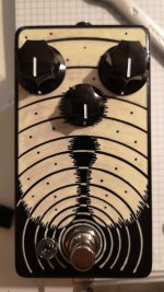
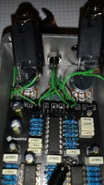
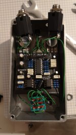
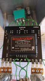
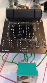
Does someone can give me any tips about what else can I check? Attached you'll find some pictures of the circuit and external box.

I'm quite new in this world, every suggestion even if its not related with this problem is very well received :)

Thanks a lot in advance!!


WhatsApp Image 2022-07-13 at 10.04.15 PM.jpeg WhatsApp Image 2022-07-13 at 10.02.38 PM.jpeg WhatsApp Image 2022-07-13 at 10.02.00 PM.jpeg
 
I am guessing the capacitor doesn't fit. It looks as if the leads are not touching anything they shouldn't, but you are just asking for trouble. I would be covering them with heatshrink just to make sure for all time.
 
The does the one pot that sits behind the board have a cover? Are you getting bypass? When you say the knobs do something are you in bypass or active? I would definitely look into the capacitor mentioned by @PJS. What does the back side of the board look like and have you tried powering it out of the enclosure. Is your LED connected correctly? Also how are you powering it
 
I am guessing the capacitor doesn't fit. It looks as if the leads are not touching anything they shouldn't, but you are just asking for trouble. I would be covering them with heatshrink just to make sure for all time.
Yes, it's too big to fit it in place and couldn't find smaller ones, it's not touching anything but I'll follow your recomendation and will cover them.
 
The does the one pot that sits behind the board have a cover? Are you getting bypass? When you say the knobs do something are you in bypass or active? I would definitely look into the capacitor mentioned by @PJS. What does the back side of the board look like and have you tried powering it out of the enclosure. Is your LED connected correctly? Also how are you powering it
It had no cover at the beginning, but now it has. Is it possible that connecting the pedal could cause a short circuit and break something?

Now I'm getting signal in both bypass and active positions. Because the led is not working, I'm not sure in which position the pots are working, but I was thiking this was active because at least it makes this small reverb.

I attatch a picutre of the back side of the board, but you will not see much because of the brick.

WhatsApp Image 2022-07-14 at 2.58.52 PM.jpeg

Now I have it out of the enclousure and it makes the same. I'm powering it with 9V quitar effects power supply.

I think that LED is well connected, long lead to K position and short lead to A position.

Is it possible that all this problems come from an attack broken pot? I think I've forced it little bit to get it in the position.

Thanks a lot!! :)
 
Oh, I', gonna try, what size is good for the capacitor?
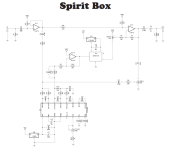
OKey, checking with the audio probe, I've find the next, but I'm not completly sure about whats normal or not.

IC1.1 TL072 All leads sound.

Path 1 going to R19:
R19 Sounds.
IC1.2 TL072 Leads 5, 6 and 7 sound
R4 Sounds.
R5 Left lead sounds neat an right lead is wet and little bit distorted. Same ase DEPTH POT. (Is this normal??)
DEPTH POT Kind of low wet signal in left and middle leads, no signal in right one.
IC2 BTDR-2H Lead 5 and 6 have same signal than Depth POT. Leads 1, 2 and 4 have no signal. Lead 3 seems like has signal coming from lead 14 from IC5 PT2399.
IC3 L78L05 has no signal.

Path 2 going to C5

C5 Sounds.
R9 Sounds. Right leg sounds like with HPF. Resistence is correct according to the lead building docs.
R13 Right lead sounds like R9 right lead and left one not. Resistence value is correct according to the building docs.
C8 Right lead sounds and left one not. Capacitor value is correct according to the building docs.
IC5 PT2399 Only 15 lead sounds good. In leads nº 7, 8, 9,12 and 14 the there is a distorsioned sound like a kind of bitcrush.
R12 Sounds.
R11 Right lead sounds like R12, left one doesn't. (Is this normal?)
IC4 TL072 None of the leads sound.
R10 Left lead sounds like R11, right lead doesn't.
IC2 BTDR-2H Lead 3 has same signal than R10 left lead.


ATTACK POT No signal
DWELL POT Good signal in left and middle leads similar at the one going out of BTDR-2H, no signal in right one

I hope it can say something to you. If there is a better way to refer to some positions for the leads in resistors or capacitors just let me know please ;)

It seems like something is wrong with PT2399, but I don't know if this is the only problem.

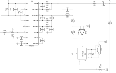
I attatch a picture of the diagram, then you can find everything easy.

Thank you in advance!!! :)

1657808252307.png
 
Last edited:
So I'll bite on this a bit. The photos aren't really helpful since we can't see the backside. From what I can see though I have some general comments. On the top side of the board some of those joints appear to be a little dry. Ideally the solder should come through the board and be visible and bond with the opposite pad as well as climb up the leg of the component a bit. Just because it doesn't look that way in the photo doesn't mean that it doesn't or that the connection is bad, but it might indicate that some joints aren't as solid as they should be. The bits we can see on the bottom look okay. You could probably bend the belton brick out of the way to get a better picture. In the places you have used wire some of those connections look like there's a bit of bare wire showing and on the pot there's some extra wire that could use a trim so that it doesn't short on something when you put it back into the enclosure.

Getting voltage readings on your IC's isn't a terrible idea if you have a DMM. As for using the audio probe you need to be methodical and following the audio path. It looks like you revised what you wrote a bit from earlier today to be a bit more thought out, which is great. When you're looking at something like the pots where you say you have no single on a particular pin, note what that pin does. It might be VCC/VREF or GND in which case not seeing audio signal there is expected. There are other places where looking for audio signal is unnecessary like IC3 and IC6 and wherever they connect since those are voltage regulators. The attack pot regulates voltage to ground, do no audio there makes sense.

If you're looking at a component in the middle of the audio path like R19 or C2 obviously you'd expect to hear something on both sides and if you're not, reflowing the joint to make sure it's actually connected and if that's good, looking for an accidental short to ground is probably next. Saying left/right doesn't really help since the orientation of the resistor doesn't necessarily correspond to the orientation in the schematic. Print yourself out a copy of the schematic or use a graphics program to work through it use a highlighter or something to note places where you have signal and where you don't, or where you find something you think is unexpected. That'll help make the picture clearer. I think you're looking in the right area for the problem, being somewhere between the PT2399 and the Belton brick. If you have additional PT2399 chips trying those might be in order as well.
First of all I want to thank you to spend this time to help me.

I have to say that after reflowing most of the connexions like you said, and now everything works!! It sounds great!!

My only question is about the PT2399 IC, because some legs still make this kind of bitcrushy noise and don't know if its normal or not. Right now i have 1, 2, 3, 4, 5, 6, 10, 11, 13 and 16 that have no audio signal. As you said it makes sense that legs 1 to 6 have no audio signal because are VCC/VREF or GND. About 10, 11, 13 and 16, all of them are IN, but really don't know if its normal to not have signal, because their respective OUTs have. Lega 9, 12, 14 and 15 have a wet kind of distorted audio signal (don't know if this small distortion is normal, but at the end of the circuit doesn't sound like this). Legs 7 and 8 have a wet and really distorted audio signal (don't know if its normal but I bet it is because those go directly to ground). Attached you'll find the diagram of the PT2399 if it says something to you.

1657978392018.png

About R10 and R11 everything still the same. One leg sounds and not the other. I don't know how to know which one on the circuit is number 1 or 2 on the diagram, either if it's normal that one leg has sound and not the other, but I can imagine it is okey as the pedal is working.

I think the pedal is working good now, every pot makes its work and sounds clean, but if you see something wrong or strange please let me know before I place it in the enclousure again. I attatch the picture from the back side of the PCB.

WhatsApp Image 2022-07-16 at 2.18.34 PM.jpeg

Now I'm gonna follow all your tips for next buildings (I have still 7 to do haha). Do you have any tip to cover some wire bonds to avoid shorts without actually undo the connection and resoldering?

Thank you all, I have learned a lot this days because of your help! :)
 
I went and dug out my spirit box build and put a probe to it and I think you're good to go. I too see the save behavior with R10/R11 and while I might not use the same terms to describe what I'm hearing at the various PT2399 pins, where I'm hearing things matches up. In my case I'd call pins 12/14 slightly delayed and not distorted. But then again maybe you don't mean actual distortion. Good work getting it fixed.
 
I went and dug out my spirit box build and put a probe to it and I think you're good to go. I too see the save behavior with R10/R11 and while I might not use the same terms to describe what I'm hearing at the various PT2399 pins, where I'm hearing things matches up. In my case I'd call pins 12/14 slightly delayed and not distorted. But then again maybe you don't mean actual distortion. Good work getting it fixed.
Hi!! Thanks for answering. It's good to know that yours works the same. About the slight distorition in pins 12/14, it's kind of a bitcrusher, but not really hard and it's delayed as yours. Maybe it's just because we have different PT2399. But now it sounds good.

Anyway, now I'm having another problem haha. Everything works perfect out of the enclousure, but when I place the jacks in its position, effect stops working. Should be some short arround, but can't find it. When this happens, should I search on the jack connections or maybe some other places to check?

EDIT: Just solved, really didn't find exactly where it was, but rechecking all connections worked well.
 
Last edited:
Back
Top