Sproing Deluxe not turning on

FurnaceRocker

New member
Hey,

I've put all the pieces of the Sproing Deluxe Reverb together, but the pedal is not turning on. I was wondering, has there been a schematic for it published yet? I feel confident in diagnosing it myself, but feel lost without a schematic.
 
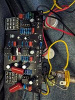
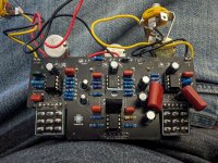
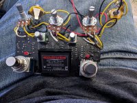
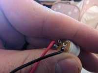
Here's a few, let me know if there's a specific angle or something.
 

Attachments

  • PXL_20240129_012540885.jpg
    PXL_20240129_012540885.jpg
    592 KB · Views: 19
  • PXL_20240129_012533183.jpg
    PXL_20240129_012533183.jpg
    636.3 KB · Views: 19
  • PXL_20240129_012516357.jpg
    PXL_20240129_012516357.jpg
    1.4 MB · Views: 19
You need to Clean all that Flux residue of the Solder side of the board first, that means bending the Reverb brick up high enough to access the solder pads underneath.
The Best cleaner is CRC CO Contact Cleaner in a spray Can, no scrubbing required!
Those 2 large caps are not the way to build a pedal!
cleaning obviously didn't do anything, and the comment about the caps is also obviously not linked to the problem of the pedal not turning on
 
Hey,

I've put all the pieces of the Sproing Deluxe Reverb together, but the pedal is not turning on. I was wondering, has there been a schematic for it published yet? I feel confident in diagnosing it myself, but feel lost without a schematic.
Can we get a little more than not turning on? Is it not turning on as in you have sound in bypass and none when you hit the switch. Is the led lighting up? Have you taken a multimeter and checked any voltages? Etc.
 
DC jack looks right.

What voltage regulator is that? Does it have the same pinout as an L78L05?
It is an L7805 voltage regulator. It does have the same pinout as the L78L05, but with you pointing it out, I realized I had it in backwards. I flipped it, and it is now outputting 5 volts. It's fixed a few of my problems, but not all unfortunately.
Can we get a little more than not turning on? Is it not turning on as in you have sound in bypass and none when you hit the switch. Is the led lighting up? Have you taken a multimeter and checked any voltages? Etc.
It doesn't output any sound at all, regardless of the switches. As well, the reverb LED does not turn on. The tremolo led does light (it flashes based on the speed knob, my understanding is that that is normal), which it didn't before I flipped my regulator. I have 9V coming in at the input jack, the 9V goes to the Reverb LED, and even shows about a 1.5V drop across it (I've changed the LED to make sure it isn't burned out and flipped it to make sure it isn't backwards, I'm not sure why it's not lighting). Each of the TL072s have +-4.5V on their VCC pins. JRC chip had about 8.3V on VCC+ and 0 on VCC-.

If there's other points that would be helpful for me to probe let me know, again without a schematic I'm feeling less sure where to look. I know I can check all the electrolic caps, but seeing the other points makes me think those DC values are what they should be.
 
It is an L7805 voltage regulator. It does have the same pinout as the L78L05, but with you pointing it out, I realized I had it in backwards. I flipped it, and it is now outputting 5 volts. It's fixed a few of my problems, but not all unfortunately.

It doesn't output any sound at all, regardless of the switches. As well, the reverb LED does not turn on. The tremolo led does light (it flashes based on the speed knob, my understanding is that that is normal), which it didn't before I flipped my regulator. I have 9V coming in at the input jack, the 9V goes to the Reverb LED, and even shows about a 1.5V drop across it (I've changed the LED to make sure it isn't burned out and flipped it to make sure it isn't backwards, I'm not sure why it's not lighting). Each of the TL072s have +-4.5V on their VCC pins. JRC chip had about 8.3V on VCC+ and 0 on VCC-.

If there's other points that would be helpful for me to probe let me know, again without a schematic I'm feeling less sure where to look. I know I can check all the electrolic caps, but seeing the other points makes me think those DC values are what they should be.
I would check your switch for continuity, or verify you’ve got the switch on the correct side. Everything that isn’t working is tied to the switch. LED lights when it see ground from the switch. Audio enters and exits through thr switch etc. and your voltages sound normal.

Sounds like it’s turning on fine
Your just not giving it any signal
 
The switch seems to be working properly in terms of continuity, and what's connected when. I can try swapping it out just to be sure, but it seems based on my probing to be working properly. It also wouldn't explain why there isn't any signal coming out of the pedal when I turn it off.

I'm giving the pedal signal.
 
Back
Top