

Texasbluezman
Member
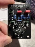
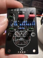
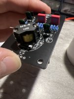
I’ve thoroughly searched and haven’t found one thread about the inductor orientation in the Station wah. What I did find said that this board, and other boards, can have about any inductor on the market. My board is different than the one pictured in the build docs. I think I have the orientation correct, but it doesn’t hurt to double check. Thanks in advance.
")


.jpeg")