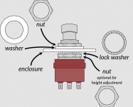
Stuff you wanted to know but were afraid to ask

There's a video where Ola Englund used one in his effects loop and compared it to putting it on front of the amp. It sounds much better in the effects loop.


I think I've also heard of people plugging into the Metal Zone and plugging it straight to the return of the effects loop, bypassing the front end of the amp altogether with good results.
 
And lots of ideas on the Internet on how to mod the MT-2 to an overdrive or even just an EQ pedal.

Would love to show up to a snobby jazz gig with an MT-2 on my bass-pedalboard... If only I knew how to play jazz, I'd DO IT!
 
And lots of ideas on the Internet on how to mod the MT-2 to an overdrive or even just an EQ pedal.

Would love to show up to a snobby jazz gig with an MT-2 on my bass-pedalboard... If only I knew how to play jazz, I'd DO IT!
or you could rehouse/disguise a few select builds inside gutted MT-2 enclosures and have the same effect 😸
 
FWIW the pre-dist voicing on the MT-2 is almost identical to the Ampeg VH140 (albeit using different circuits - gyrator vs. feedback loop hacks). Where the difference becomes noticeable is in the post-dist controls and voicing (big presence and resonance bumps + different tonestack). OK, clipping levels and methods are different, but at brute gain it is not that big of a deal. I think one can get good results in tinkering with the last stages, especially lowering the hi treble bump.
 
FWIW the pre-dist voicing on the MT-2 is almost identical to the Ampeg VH140 (albeit using different circuits - gyrator vs. feedback loop hacks). Where the difference becomes noticeable is in the post-dist controls and voicing (big presence and resonance bumps + different tonestack). OK, clipping levels and methods are different, but at brute gain it is not that big of a deal. I think one can get good results in tinkering with the last stages, especially lowering the hi treble bump.
that's probably why it rules, VH1404Lyfe
 
Given: Many pedals with a 9v battery installed will slowly drain if left with the input jack plugged in.

Question: If there is a 9V source also plugged into a switched jack but not applying power, will the battery still drain? i.e. Does plugging into the jack short the battery (+)? TIA
 
Given: Many pedals with a 9v battery installed will slowly drain if left with the input jack plugged in.

Question: If there is a 9V source also plugged into a switched jack but not applying power, will the battery still drain? i.e. Does plugging into the jack short the battery (+)? TIA
No. If wired correctly the swit8ches DC jack should open the battery feed
 
No. If wired correctly the swit8ches DC jack should open the battery feed
Thats because typically the input jack is shorting the "ground" (typically, but not always negative). That one's like a normally open set of contacts: inserting a mono plug into a stereo jack that has the load (circuit) tied to the ring and the "ground" tied to the barrel shorts the ring and barrel together. Boom. You've got continuity and a complete circuit.

The way this is achieved with a DC jack, typically, is through a normally closed switch on the barrel plug and whatever the circuit is using for "hot" (typically, but not always positive).

The circuit exists on the common side of the switch, the 9v battery exists on the normally closed side of the switch. Insert a barrel plug and the normally closed contact opens: the barrel jack physically pries two pieces of metal apart, so the battery is disconnected.
 
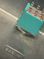
Anybody got experience with Vishay DG469 analog switches? Link to datasheet below. Just need a second set of eyes to confirm I got the switching logic right (or not). So, with the IN pin floating, the n/c pin connects to common and the n/o pin is essentially left floating. And when the IN pin is grounded, n/o connects to common and n/c is left floating. Yes, no?


Edit: Reading more about analog switches it seems I didn't get it right. IN should never be left floating and to connect the n/c pin to common, IN needs to have some voltage applied to it?
 
Last edited:
So… SMD layouts/components

I’ve searched and more or less want to confirm what i’ve found across several sources on the interwebs.

Film caps mostly become C0G MLCC caps? except for higher values some prefer through hole films? Package size 805?

Thick film resistors? Package size 603 or 805?

Kemet, muRata, TDK?

I’m just looking for general rules. I am no engineer or mathematician but i like to try to make sure things are done right.
 
Anybody got experience with Vishay DG469 analog switches? Link to datasheet below. Just need a second set of eyes to confirm I got the switching logic right (or not). So, with the IN pin floating, the n/c pin connects to common and the n/o pin is essentially left floating. And when the IN pin is grounded, n/o connects to common and n/c is left floating. Yes, no?


Edit: Reading more about analog switches it seems I didn't get it right. IN should never be left floating and to connect the n/c pin to common, IN needs to have some voltage applied to it?
IN is the logic input and ought not be left floating. "COM", "NC" and/or "NO" can be left floating - those control the signal path. "IN" is the logic that toggles the switch.
 
So… SMD layouts/components

I’ve searched and more or less want to confirm what i’ve found across several sources on the interwebs.

Film caps mostly become C0G MLCC caps? except for higher values some prefer through hole films? Package size 805?

Thick film resistors? Package size 603 or 805?

Kemet, muRata, TDK?

I’m just looking for general rules. I am no engineer or mathematician but i like to try to make sure things are done right.

This has been my general approach but #IHaveNoIdeaWhatI'mDoingDog.

C0G/NP0 caps for anything in the audio path, X7R/X5R for IC decoupling/power filtering caps. Mostly muRata
which is generally available on LCSC/JLC for the C0G caps. In terms of physical size, you're limited by what's
offered. Smaller (pF) come in 0603, low/mid nF in 0805, and the larger ones (47/100/220nF) only come in 1206.

If you're using JLC, pay special attention to 'Basic' and 'Extended' components, you'll want to use as
few *different* extended components as possible, because each different one adds $3 setup to the PCBA cost.
The caps might be 0.015, but it costs $3.015 to put the first one on a batch of boards.
Some values come in multiple footprints but one might be Basic and the other Extended. (e.g. there are
some pF size caps that are basic in 0603 but extended in 0805).

Often I'll do extended component golf and use 2x47nF in parallel instead of a 100nF because I already
have 100nF caps elsewhere, or even like 10nf + 10nf + 2.2nf for a 22nf cap. When you're only making
10 boards at a time, the startup costs end up being a significant part of the whole, so if you can replace
an extended part with less than 30 cents worth of other components (for 10 boards) it's worth it if you
have the space in the layout. Obviously the more boards you order at a time, the less the setup-cost-per-board
is, so you don't need to worry as much. After 50 boards you have to pay $3/component type anyway.

This can also be a decider for me whether or not to use a box style film cap. You can get up to 220nF
generally-available in C0G but sometimes if I only need a value once or twice and there's room I'll slap
a box cap on there and call it good. Also anything larger than 220nF I'll use the box cap. For the most
part I leave those unpopulated via PCBA and hand solder them at home, although I do have them solder
other through-hole components like connectors and trimpots.

For resistors I've been using the 'Basic' 0603 size (Uni-Royal brand).

Also one thing that's nice is that there are 'Basic' versions of quite a few op-amps (TL072, LM386, NE5532)
for ~10 cents so sometimes if routing both halves of a dual op-amp are painful you can just say screw it
and drop another one in. (Or if you're worried about LFO noise, or you want to get an extra half to drive
an input buffer or vref or something)

All of this sounds fine to me but I'm a half-deaf old man that wouldn't know tone if it shouted me in the face.

I guess I should write a "Getting started with JLC PCBA post" if that doesn't already exist!
All of this is incredibly helpful!! Thank you!!
 
All of this is incredibly helpful!! Thank you!!

Glad it was useful! I cleaned it up a bit and added a little more stuff and posted it here:

Maybe it's worth sticky-ing (high hopes)

Also here:
 
  • This ROCKS!
Reactions: spi
Back
Top