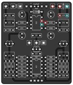
SOLVED Sugarbag Overdrive no signal

Fama

Well-known member
First off, I apologize for the abomination of a build. I first put in the 2N5088 in the wrong orientation, clipped off the legs and tried desoldering for a bit, but it didn't work very well so I just soldered a new one on top. I also subbed two of the 1uF coupling caps (?) for 470nF due to lacking 1uF parts. And finally C100 is two 4.7nF caps instead of a 10nF cap.

So, I'm not getting any signal through. I tried audio probing, R1 is fine on one end, nothing on the other (since it's grounded, obviously), R2 is fine on one end, and very quiet, thin and distorted on the other end. I get the same thin, very distorted sound on pin 2 of IC1 and also on one side of R3. Nothing on any other pins of the TL072.

R2 seems to be the correct resistance, it measures as 390k. However, R1 measures at 0.04 ohms or so, while I think it should be measuring correctly if everything was ok? The bands match up with 10M that it's supposed to be. My DMM doesn't go higher than 2M, but it just shows 0.00 at max setting, and with the lowest resistance setting it shows 0.04-0.06 or so. Edit: I'm dumb, when the footswitch is on bypass, the PCB input is grounded, so of course R1 measures as zero. When I switch the footswitch it doesn't register anymore, which it should, as the DMM only goes to 2M like I said.

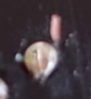
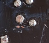
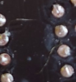
There are also a couple of scrapes on the underside of the board where the copper shows through which I was afraid might have ruined the board, but I don't think the signal should stop that early if that was the case.
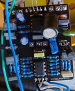
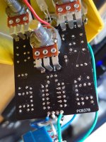
DSC_2663.JPG
DSC_2662.JPG
 
Last edited:
Solution
After doing a bunch of things, I got a decent sounding signal all the way to pin 7 of IC2, but not to R20. I then made a solder bridge from IC2 pin 7 to the same end of R20 where C11 connects to. Now I get a signal - but it feels like there's too much gain, it's basically a farty fuzz and the volume pot doesn't make any difference. But at least there's progress.
You may have a Dud Volume Pot?
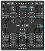
Here is a Continuity test for all connections to the Volume pot.
Make sure Pin 7 & Pin 6 are not bridged!, no Continuity.
Volume Pot ContinuityTest.jpg

It is more Overdrive into Fuzz with a Clean Amp:
What voltages are you getting on each of the IC pins?
IC1:
1: ~6.6
2: ~6.6
3: ~6.6
4: 0
5: 3.3
6: ~6.6
7: ~6.6
8: ~13.3

IC2:
1: ~6.6
2: ~6.6
3: ~6.6
4: 0
5: ~6.6
6: ~6.6
7: ~5.5
8: ~13.3


I followed this pinout, I assume it's standard https://www.componentsinfo.com/wp-content/uploads/2021/09/tl072-pinout-equivalent.gif

Edit: That's with volume and gain at full if it's relevant.

Edit2: I started wondering how I'm getting 13V on a 9V power supply, and I think I'll just stop using that one. It's a separate small power supply for a Zoom pedal, although it claims it should output 9V DC. I tried with the normal power supply I use and got the following results:


IC1:
1: ~4.4
2: ~4.2
3: ~4.4
4: 0
5: ~1.8
6: ~4.5
7: ~4.4
8: ~8.9

IC2:
1: ~4.4
2: ~4.4
3: ~4.4
4: 0
5: ~4.4
6: ~4.3
7: ~4.6
8: ~8.9

I'll repeat the audio probe test again with the correct supply soon, or I'll see if I have another supply I could use to test it so I don't have to sit on the ground while audio probing.

Edit3: Switched to a Boss supply for the Test Rig I'm using as the audio probe, same as before. One side of R1 fine, both sides of C1 fine, one side of R2 fine, other side of R2 thin, quiet and distorted. Same thing, quiet and distorted sound going in pin 2 of IC1, nothing on any other pin of IC1. Pin1 of gain pot, R3 and I assume pin 2 of C2 also give the same quiet and distorted sound, pin 1 of C2 (I assume) gives nothing.

I guess I should try reflowing R2 then? It looks fine to me, but just to be sure.

Reflowed R2, no help.

I also tried an another TL072CP, no change.
 
Last edited:
There are also a couple of scrapes on the underside of the board where the copper shows through which I was afraid might have ruined the board, but I don't think the signal should stop that early if that was the case.
Screenshot 2023-08-11 at 19-34-27 Sugarbag Overdrive no signal.png Screenshot 2023-08-11 at 19-33-46 Sugarbag Overdrive no signal.png
I would perform a continuity test to make sure the traces aren't cut at these 2 locations. Check the schematics to see what are the connections with these pads.
Edit 2 : if it's cut, no worries, all you have to do is add a jumper to restore the connection.


Screenshot 2023-08-11 at 19-34-10 Sugarbag Overdrive no signal.png
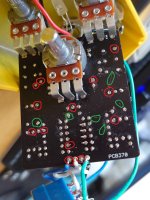
I would clean these residues with my iron, and perform some more continuity tests, following schematics, to make sure there aren't any shorts at every locations where i can spot some residues.

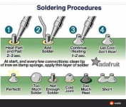
Check this build report, you'll find a better way to clean the residues :


Edit : Green possible short, Red possible bad solder joint (we can see the pads aren't filled with solder).
DSC_2662.JPG
8sn3zzvvccg71.png
 
Last edited:
Your voltages look good. Your soldering is not the worst.

I would try swapping out IC1 for another one if you have it- or swap IC1 and IC 2 over if you haven't. Also, test the gain pot to make sure you are getting a full sweep of resistance from 0 to 1M. If that pot is faulty you could get bad things happening.
I swapped IC1 out for another one (tried two others, even), no change. If I take IC1 out, I get guitar signal (weak and muddy) from IC1 pin 1 too (presumably through the feedback loop? Is that supposed to happen?), and then it goes to Q1 pin 3, but not to Q1 pin 1.

With IC1 in place, no signal goes to IC1 pin 1.

Gain pot seems to work ok, I get 0 to 1M as I should, and the gain pot affects the quiet distorted signal that I do get going into the IC1 pin 2.
 
If you end up not being able to fix this, I have a working one I built that I never put in an enclosure you can have. You’ll just need to put it in an enclosure.
 
If you end up not being able to fix this, I have a working one I built that I never put in an enclosure you can have. You’ll just need to put it in an enclosure.
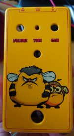
Thanks for the offer, I'm in Finland so the shipping might be a bit much, but if I can't get this fixed I might as well pay whatever it is (as long as it's not like $50 or so) since I really like the "Don't talk to me or my bee son ever again" look on the enclosure. But I'll try if I can get this fixed first.

DSC_2669.JPG
 
Thanks for the offer, I'm in Finland so the shipping might be a bit much, but if I can't get this fixed I might as well pay whatever it is (as long as it's not like $50 or so) since I really like the "Don't talk to me or my bee son ever again" look on the enclosure. But I'll try if I can get this fixed first.

View attachment 54453
That enclosure is awesome! Yeah man just let me know. I’m in Michigan. Shipping shouldn’t be too awful.
 
These all check out too. And C3 being 470nF instead of 1uF shouldn't change anything, right?

I appreciate all the help so far! I'll do a reflow of any suspicious looking solder joints now to see if that helps.
IC1 Pin 5 is too low, it should be around 4.5v
Was C6 damaged when pushed down or C101???
 
IC1 Pin 5 is too low, it should be around 4.5v
Was C6 damaged when pushed down or C101???
They look ok.

I tried hooking up my TC1 (using the remote hooks it came with), C101 measures as 424uF with 1.5% Vloss and ESR of 0.41 ohms, but C6 doesn't measure at all. I'm not sure if this could be an anomaly caused by measuring it in the circuit itself, but I'll probably try replacing it - that will take until tomorrow though. But that's the best lead so far!
Test 3:

Sugarbag ContinuityTest 3.jpg
 

Rarely, if ever, is the issue a bad cap or resistor. Randomly pulling components will cause more harm than good. A lot of your solder joints could use more solder. It should flow through the board. You’d be surprised how many times this fixes the issues. You really can’t tell a whole lot by eyeballing it. R2 isn’t your issue, it’s something after.

We’re all over the place with our troubleshooting. We need to be more methodical about it.

1. After you’ve checked all your values and reflowed / added solder, pull IC1 and see if you have audio on pin 2 and R3.
2. If you don’t let’s look for a short to ground with your DMM.
There is definately not enough heat in the soldering as all the resistors lack penetration on the top side so a hotter Iron may be needed!??
C6 definately needs to be pulled as it's going to ground & he should be getting a reading!???
Test 3 is my final Continuity test for the transistor & surrounding connections.
I am not a fan of those transistor sockets, I hope those J113's are from a reliable source???
 
These all check out.
Rarely, if ever, is the issue a bad cap or resistor. Randomly pulling components will cause more harm than good. A lot of your solder joints could use more solder. It should flow through the board. You’d be surprised how many times this fixes the issues. You really can’t tell a whole lot by eyeballing it. R2 isn’t your issue, it’s something after.

We’re all over the place with our troubleshooting. We need to be more methodical about it.

1. After you’ve checked all your values and reflowed / added solder, pull IC1 and see if you have audio on pin 2 and R3.
2. If you don’t let’s look for a short to ground with your DMM.
1.) I already tested that (although you're right, I have not been methodical at all about this so it's easy to miss it), with IC1 pulled I get audio on pin 2 and also pin 1 (both are muffled and a bit quiet). With IC1 in place, pin 2 has quiet and distorted audio and nothing on pin 1. R3 I think also has the same quiet audio.
There is definately not enough heat in the soldering as all the resistors lack penetration on the top side so a hotter Iron may be needed!??
C6 definately needs to be pulled as it's going to ground & he should be getting a reading!???
Test 3 is my final Continuity test for the transistor & surrounding connections.
I am not a fan of those transistor sockets, I hope those J113's are from a reliable source???
Yeah, I have a perpetual problem with the tips oxidizing (I assume from not turning the iron off every time when I put in more components, maybe?). I tried adding a lot of solder to it to protect it from oxidizing, but then it felt like my brass sponge was starting to fill up with solder very quickly so that didn't feel like a good solution either.

I cleaned it with a sal-ammoniac stone or whatever you call it so it's good now (for some time). But that's also a pain because I have to make sure the cats away, then do it carefully and let the room air out. I probably should get some sort of breathing protection or something I guess, no option to do it outside I'm afraid.

I don't think the transistor sockets are amazing either, but I only had J112's when I started this so thus the sockets so I could switch to J113's when they arrived. And they seem to get continuity no problem.

J113's are from LCSC electronics, or technically they're J113-D74Z (plain J113 were out), but as far as I could determine that just means they come in a different packaging than the normal ones (or at least would come in bulk). I also tried swapping them out for J112's (which I think should work as replacements since they're the same part, just binned for performance?) with no change, so I don't think there's any issues with those.
 
Back
Top