You are using an out of date browser. It may not display this or other websites correctly.
You should upgrade or use an alternative browser.
You should upgrade or use an alternative browser.
THAT 2159 chip supplier?
- Thread starter cooder
- Start date
IPv6Freely
Active member
Here you go!

 smallbear-electronics.mybigcommerce.com

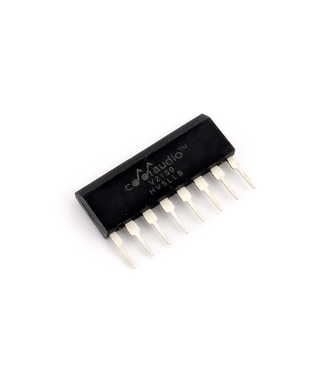
V2159D VCA IC SIP-8
New England's source for guitar pedals, pedal parts and electronics.
IPv6Freely
Active member
I'm still waiting on the non-standard capacitor values to arrive. I'm sure I could replace the 50p with 47p, but still...This comp is killer too. I've never played the original but it's a nice middle of the road between all the non-opto variants out there. The V2159D is really smooth and very quiet. It's not boxed up yet but this one is a keeper.
fydo
Well-known member
Sorry to resurrect an old thread. Since Smallbear is out of stock (has been for a while) and every eBay listing for THAT2159 appears to be a fake from China, I just wanted to ask if anyone has a source on a THAT2159, CoolAudio V2159D or any appropriate replacement? I've been excited to build the Creamery but this has been a roadblock for me.
Thanks in advance!
Thanks in advance!
jimilee
Well-known member
Have you checked cabintech?Sorry to resurrect an old thread. Since Smallbear is out of stock (has been for a while) and every eBay listing for THAT2159 appears to be a fake from China, I just wanted to ask if anyone has a source on a THAT2159, CoolAudio V2159D or any appropriate replacement? I've been excited to build the Creamery but this has been a roadblock for me.
Thanks in advance!
fydo
Well-known member
Yes, I had a look through their Semiconductors page ( http://cabintechglobal.com/semi ) since I know they stock some CoolAudio products but there aren't any 2159's there currently. I appreciate the suggestion though!
bowanderror
Well-known member
The 2159 is just a bottom of the barrel spec'd 215x-series VCA. You should be able to replace it with a 2155, 2150, or 2151. The specs, and therefore costs, increase as you go from 2155 to 2150 to 2151.
These will still be hard to find, as they have been mostly replaced by the 2181 & 2180 series. The 2181 is supposed to be a drop-in replacement for the entire 215x-series, with one caveat: The 2181 is designed with an internal trimmer resistor. This means you'll have to leave out the resistor in the 215x design that links pin 2 & pin 4, as well as adjusting the value of the symmetry voltage divider resistor (from your sym trimpot). If you're interested in using the 2181, I suggest looking at this THAT design note, which has all the details.
These will still be hard to find, as they have been mostly replaced by the 2181 & 2180 series. The 2181 is supposed to be a drop-in replacement for the entire 215x-series, with one caveat: The 2181 is designed with an internal trimmer resistor. This means you'll have to leave out the resistor in the 215x design that links pin 2 & pin 4, as well as adjusting the value of the symmetry voltage divider resistor (from your sym trimpot). If you're interested in using the 2181, I suggest looking at this THAT design note, which has all the details.
almondcity
Well-known member
Man I picked up two more cool audio 2159 from small bear a few weeks ago because I saw they were selling out. I think I'll pick up another board here during the sale. I might try and figure out the 2181 chip. If I can I may have the 2159s to spare
I'm building a madbean oracle which has the 2181 but only one of them, not sure why this pedal has two
I'm building a madbean oracle which has the 2181 but only one of them, not sure why this pedal has two
almondcity
Well-known member
FYI I just tried that 2181 in both positions of this circuit with no modifications and it appears to work exactly the same
Cabintech
Authorized Vendor
I don't think there is a Coolaudio 2159 currently in production.Yes, I had a look through their Semiconductors page ( http://cabintechglobal.com/semi ) since I know they stock some CoolAudio products but there aren't any 2159's there currently. I appreciate the suggestion though!
almondcity
Well-known member
You could try the that 2181 as it worked similarly in my experienceHowdy, I’ve been looking into the creamery compressor and obviously it uses the that2159. Does anyone out there know a current legit source for these or are interested in parting with a pair?
I'd also recommend the madbean trash compactor as an alternative for this circuit as it's parts are all available
Bricksnbeatles
Member known well
To revive this thread– In the Creamery schematic, if using the 2181 in place of the 2159, R31 is to be omitted as it correlates to the 2181 Design Note Page's R2 for IC2.
For IC5, there doesn't seem to be a connection between pin 2 and pin 4, or rather there is, but it's via a 33k resistor- R23. This configuration however bares similarity to figure 7 and figure 8, which would suggest that R23 is comparable to R3, which the Design Note Page suggests should be calculated for minimum THD via the datasheet, but the fact that pins 2 and 4 have an internal 25Ω connection, and both are connected to Vref in IC5 would suggest that R23 is completely inconsequential since it would no longer be providing any function other than to reduce the internal resistance of pins 2 and 4 from 25Ω to 24.98Ω; that said, no point in omitting it since it doesn't do any harm.
Now– R32 has a lot in common with R3 with regard to IC2, but I can't seem to find in the 2181 datasheet where it says how to calculate what size that resistance should be given the supply voltage– that said 1K for R32 definitely seems way small compared to the 130k-680k values given for R3 when assuming a bi-polar 15v supply, so I'm not sure what, if anything, to change R32's value to.
Anyone else have any thoughts on my observations, or any further insights into what should be changed when using a 2181 in place of the original 2159?
comradehoser
Well-known member
How did this end up?
Having some odd over-level stuff in my creamery built with 2181Cs when hi-ex is engaged
Having some odd over-level stuff in my creamery built with 2181Cs when hi-ex is engaged
Erik S
Well-known member
I haven't been following this whole saga, but it looks like Robert's got em.Did anyone get any wiser regarding using the 2181 as a replacement for 2159?

Similar threads
- Replies
- 7
- Views
- 372

