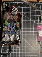
It still like your input and output are wired incorrectly.
The long springy bit that touches the tip of the 1/4" plug is what connects to the switch daughter board, it looks like you have those connected to the ground buss on the PCB.
Typically, Tip= signal, ring=ground.
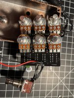
As for the LEDs, have you double checked polarity on those? It's real easy to get them backwards, PedalPCB does it the "correct" way, but the correct way can seem a little counter-intuitive. The short lead on an LED goes to the square pad, the long lead goes to the round pad. The positive lands on A(node) and negative lands on K(athode...cathode. not sure why it's a K).
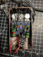
Also, take a look at your wire-to-board connections. It looks like you're using a non-prebond-stranded wire; It's the stuff that I typically prefer to use honestly, but it has a tendency of fraying out and causing shorts on either side of the PCB.
I'd recommend cutting off the excess from the terminated side, and cleaning up any strands that might have gone astray. All it takes is one strand, thinner than a hair, to cause a short. They can be difficult to see...headband magnifiers are hugely helpful in this case.
If none of that helps, post your opamp voltages, that can help narrow down where the problem is.


")
