This Week on the Breadboard: The Celestial Boost

In Australia we call it shit-stirring. I have been called a shit-stirrer many times. It is considered a noble art here by the cognoscenti. Some of our most famous exports have been shit-stirrers. And New Zealand has some of the finest. The Kiwi sense of humour can be amongst the world's driest.

You said something about pedals?
 
@Chuck D. Bones - I want to build the boost-only circuit. Is the first schematic you posted still considered good for that? Or is the tweaked more complex circuit in boost mode better than the boost-only circuit?
If all you want is clean boost, then the circuit in post #1 will get you there. At higher GAIN settings, less bass gets thru Q1. You can compensate for that by adjusting the BASS knob. The way I would set the knobs is start with BASS & TREBLE at 5, VOLUME at 10 and adjust GAIN for the desired boost. Then adjust the EQ.

And if that first boost only circuit is still viable, should Q1's drain be set for 5.4v as in the latter circuit?

Select Q1 to get close to 5.4V when GAIN is dimed, then fine-tune by adjusting R6. Try to keep R6 between 35K and 45K for best results. Note that the GAIN knob affects the bias and might scratch when turned.

If you don't need the clipping option, then omit S2, D1, D2 & C15. For maximum headroom, omit D3 & D4. If you take all four (D1-D4) out, then you can omit R7 and jumper C3.

I tweaked the clipping section slightly, with an ON-OFF-ON switch, so you can have all three options (max headroom, LED clipping, 2n4148 clipping).

I made R6 33k in series with a trimpot.
 

Attachments

Last edited:
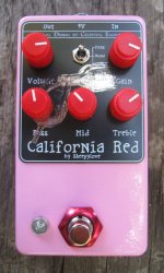
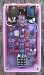
I built up a prototype based on the boost-only schematic posted above. Some questions...

For the J113 Vp, per these instructions:
Vp is easily measured with a DMM and a 9V power supply (or battery). Connect JFET Drain to +9V with a 10K resistor in series. The resistor is there to protect the JFET in case you hook it up wrong. Connect Gate to the minus side of the power supply or battery. Set DMM to measure voltage. Connect DMM from Gate to Source (+ lead on GATE). The DMM will read Vp. Vp will be a negative number.

In this scheme, the JFET source pin is left open (only connected to the DMM), right?

Assuming I measured the the JFET correctly, the closest to the suggested 2.1v I had was 2.0v. (All the others were <2.)

Select Q1 to get close to 5.4V when GAIN is dimed, then fine-tune by adjusting R6. Try to keep R6 between 35K and 45K for best results.

I went with 27k for R6 and used a 25k trimpot. But even with the trimpot fully clockwise, I'm maxing out at 5.0v on Q1's drain. Should I further drop R6, even though I'm already well-below the 35k you suggested?

Despite the numbers being off, it works and sounds more or less like I expected. I find the gain knob doesn't seem to do much, other than increase volume, until the last 1/3 of the rotation. Note I didn't have a C50k pot, so I used a C100k pot and put a 100k resistor across pins 1 and 3.

It's definitely a boost, as there's a massive amount of volume available!

Not my prettiest work, but it is a prototype. But it's a working prototype!
 

Attachments

  • IMG_1125.jpg
    IMG_1125.jpg
    372 KB · Views: 6
Hey Matt, nice build.

You're referring to the schematic in post #1, right?
27K is ok for R6. You're giving up a little gain, but no biggie.

You'd be better off with a C50K pot because putting 100K in parallel with a C100K pot undoes some (most?) of the C-taper. This makes the pot do just what you describe.
 
You're referring to the schematic in post #1, right?
27K is ok for R6. You're giving up a little gain, but no biggie.

Technically, the schematic in post #73 above, but it's essentially the same as #1.

You'd be better off with a C50K pot because putting 100K in parallel with a C100K pot undoes some (most?) of the C-taper. This makes the pot do just what you describe.

Ahh, yes, I should have caught that! I suppose the parallel trick probably works best for linear taper pots, right?

Anyway, thanks! Great circuit, and I have spare PCBs for anyone who wants one!
 
The parallel trick will change any taper and has the most effect when the pot approaches maximum resistance. With C-taper, the pot is at minimum resistance near full CW, when means the parallel resistor has almost no effect there. However, a C100K pot has twice the resistance of a C50K at any position, so it will be twice as sensitive at the CW end of rotation.

A better way to chose the best JFET is to either install a socket on the board or to breadboard the first stage and try different JFETs to find ones that give the desired drain voltage. Since it's a DC test, you can leave the capacitors out for the breadboard test.
 
Back
Top