Tone vendor bender mk2 bias

Rimgrot

New member
Hi!
I'm currently building a Tone Vendor mk2. Bought a transistor set from Smallbear which came with the following components:
Q1 2n1305 - hfe: 67, leakage 40
Q2 OC75 - hfe: 70, leakage 270
Q3 2n1305 - hfe: 103, leakage 10

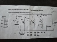
Smallbear suggest the following bias resistors:
R3 100k (R5 on the tone vendor pcb)
R4 91k
R6 6.2 k (R7 on the tone vendor pcb)

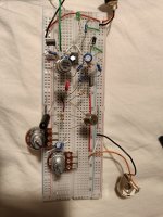
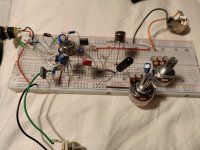
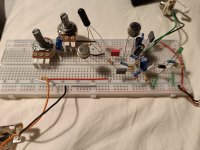
I have breadboarded the circuit and It works, but output volume is a bit low, about unity gain with the volume pot maxed. And the fuzz sounds undefined and gated/little sustain with attack pot on max.

The collector voltages with 9v power supply are:
Q1 c 8,29V
Q2 c 0.178V
Q3 c 8,7V

Is it possible to bias this circuit better? I have not tried any other Tone Bender circuits before so I am a bit unsure what I am aiming for and how it should behave.
Thanks!
 

Attachments

  • IMG20230424203039.jpg
    IMG20230424203039.jpg
    445.7 KB · Views: 19
Hello, welcome !

You can have a look at Aion's tonebender mk2 build docs (p.5, 6) for more info about the biasing :


If you want to be be as accurate as possible, i guess you have to use some trimmers to set the bias resistance. Once you found the right values, you can solder the proper resistors.
I have not tried any other Tone Bender circuits before so I am a bit unsure what I am aiming for and how it should behave.
If you can't compare with an original unit, you'll have to trust your ears, and find the sound that suits you the most.

From what I could gather, you chose to build the most difficult tonebender version. Mk3 is easier.

"Germanium transistors are notorious for being extremely temperature-sensitive, and as the ambient
conditions change, gain and leakage can vary drastically.
(...) if you notice the unit get noisier as the seasons get colder, it’s probably because Q1 is not
consistently leaky enough. If you can’t change the ambient conditions then you might need to change
the transistor for one that has an even higher leakage."
 
Last edited:
Hello, welcome !

You can have a look at Aion's tonebender mk2 build docs (p.5, 6) for more info about the biasing :

If you want to be be as accurate as possible, i guess you have to use some trimmers to set the bias resistance. Once you found the right values, you can solder the proper resistors.
Hello, and thank you for answering. I have looked at the docs from Aion and will try putting some trimpots on my breadboard. I happened to have both a 10k and a 50k trimpot so will see if I can get it sounding better.
Will a more correct bias also affect output volume?
One of the reasons for posting in this forum was that I have seen many different recommended collector voltages for this circuit (from 7-9V on Q1 and Q3), so was also hoping for some insight regarding what voltages in comparison to Hfe and leakage, if that makes any sense.

If you can't compare with an original unit, you'll have to trust your ears, and find the sound that suits you the most.

From what I could gather, you chose to build the most difficult tonebender version. Mk3 is easier.
I also got a matched set for a mk1 from small bear, but thought it would be easier to start with the mk2 since it had been tested and came with recommended bias values.
 
Have you tried using the stock values instead?

In my limited experience with the circuit, an MKII should sound like a Fuzz Face but with more gain and more treble (with Attack maxed out). It should should huge.

It should still clean up completely by rolling the guitar down to 2.

If you lower Attack, it should clean up at around 5, so basically like a Fuzz Face.

If you want more output, lower the 8.2k resistor on Q3c and increase the 470R accordingly to maintain the same total resistance. However those voltages are not set in stone. Anything from -8V to almost -9V should work.
 
Hello, welcome !

You can have a look at Aion's tonebender mk2 build docs (p.5, 6) for more info about the biasing :


If you want to be be as accurate as possible, i guess you have to use some trimmers to set the bias resistance. Once you found the right values, you can solder the proper resistors.

If you can't compare with an original unit, you'll have to trust your ears, and find the sound that suits you the most.

From what I could gather, you chose to build the most difficult tonebender version. Mk3 is easier.

"Germanium transistors are notorious for being extremely temperature-sensitive, and as the ambient
conditions change, gain and leakage can vary drastically.
(...) if you notice the unit get noisier as the seasons get colder, it’s probably because Q1 is not
consistently leaky enough. If you can’t change the ambient conditions then you might need to change
the transistor for one that has an even higher leakage."
I think the MKI is the hardest to build because unless you have just the right amount of fuzz and leakage it sounds weak or too dark and it's full of ugly artifacts in the decay of the notes.

The key to all Tone Benders is enough leakage. It naturally brings the voltage to the right spot without losing the fuzz character.

The problem is the seeming randomness in the response of transistors. Some that should work don't and others that shouldn't work do.
 
Hi!
My power supply is putting out 9.03V. I'm building the circuit with the TC1044, and pin 5 on the IC reads -8,79V

I would inspect the board and your joints. You are not getting much voltage dropped across the Q3 collector.

Even with that thought, the voltages are high. Furthermore, Steve at small bear used erroneously target 4.5 vDC on Q3 and his resistor values reflected that. Assuming Synth Cube uses his notes for testing, something is certainly amiss.

Your output issues are almost certainly
Because of extreme gating.

First rule out poor craftsmanship and soldering and then we can start working on tweaking the bias.
 
Have you tried using the stock values instead?
Hi, and thanks for replying! I tried the stock values first (Tone vendor-values). They sounded worse as in more gated and little sustain. The circuit sounds a little better with the bias values from small bear.
In my limited experience with the circuit, an MKII should sound like a Fuzz Face but with more gain and more treble (with Attack maxed out). It should should huge.

It should still clean up completely by rolling the guitar down to 2.

If you lower Attack, it should clean up at around 5, so basically like a Fuzz Face.

I recently built a fuzz face which turned really great. Compared to that this bender circuit doesn't sound huge and not so trebly. The bender cleans up a little bit, but not in the same way as the fuzz face

If you want more output, lower the 8.2k resistor on Q3c and increase the 470R accordingly to maintain the same total resistance. However those voltages are not set in stone. Anything from -8V to almost -9V should work.
Thank you for suggestions regarding output volume. Will try this after tinkering with the bias resistors.
 
I would inspect the board and your joints. You are not getting much voltage dropped across the Q3 collector.

Even with that thought, the voltages are high. Furthermore, Steve at small bear used erroneously target 4.5 vDC on Q3 and his resistor values reflected that. Assuming Synth Cube uses his notes for testing, something is certainly amiss.

Your output issues are almost certainly
Because of extreme gating.

First rule out poor craftsmanship and soldering and then we can start working on tweaking the bias.
Thank you for responding. I haven't soldered the components to the PCB yet, it is still on my breadboard. I have checked for continuity and that the components and values are correct with my DMM.

I have attached some pictures of the breadboard, though it is difficult to make out connections on the photos.
 

Attachments

  • IMG20230425135452.jpg
    IMG20230425135452.jpg
    580.4 KB · Views: 10
  • IMG20230425135506.jpg
    IMG20230425135506.jpg
    471.9 KB · Views: 10
  • IMG20230425135528.jpg
    IMG20230425135528.jpg
    561.6 KB · Views: 10
Even with that thought, the voltages are high. Furthermore, Steve at small bear used erroneously target 4.5 vDC on Q3 and his resistor values reflected that. Assuming Synth Cube uses his notes for testing, something is certainly amiss.
The supplied voltages are with the suggested bias resistors from small bear:
Q1 c 8,29V
Q2 c 0.178V
Q3 c 8,7V
 
What happens when you change R1 and R7 to 10k?
Here are the voltages with R1 and R7 as 10k:
Q1
C. 8.67V B. 11mV E. 0.00
Q2
C. 250mV B. 85mV E. 0.00
Q3
C. 8.58V B. 250mV E. 190mV

I am assuming you meant R1 and R7 from the pedalpcb schematic.
It's a bit late so can't test how this sounds until tomorrow.
 
Here are the voltages with R1 and R7 as 10k:
Q1
C. 8.67V B. 11mV E. 0.00
Q2
C. 250mV B. 85mV E. 0.00
Q3
C. 8.58V B. 250mV E. 190mV

I am assuming you meant R1 and R7 from the pedalpcb schematic.
It's a bit late so can't test how this sounds until tomorrow.

Try that and I have more tweaks to try as well.
 
Try that and I have more tweaks to try as well.
Ok, have tested it with 10k in R1 and R7.
To me it now sounds more destroyed and reminds me a bit like a bit crusher. I think the volume output is a bit higher, and the notes sustain for a while, but the dynamics when I pick the notes is very flat and compressed. Chords or more than one note sounds very mushy and undefined.
Overall I think I liked the sound better as it was before.
I can try to upload a recording if that is helpful?

I’d keep dropping the voltage. Give me a few minutes to consult my notes and as long as you are still on the breadboard, we should be able to sort it out.
 
Can the gated sounds in the decay be caused by the biasing of Q3 or a combination of all the transistors?
not sure if its helpful but i have heard that using a starve pot to lower voltage can cause gating in these 3 germanium transistor builds.
 
Can the gated sounds in the decay be caused by the biasing of Q3 or a combination of all the transistors?
not sure if its helpful but i have heard that using a starve pot to lower voltage can cause gating in these 3 germanium transistor builds.

His voltages are just way too high. Vintage MK II units varied but a generally accepted point for the onset of gating is around 8.2 vDC.
 
FWIW . . .. here are some links to BJT Biasing Calculators . . . .
(I just Googled "transistor biasing calculator" and got a good list of sites.)

Transistor Biasing Calculator

Calculator Edge

Peter Vis

Alan Yate's BJT Biasing

Personally, I prefer to use trimpots as biasing elements when breadboarding Ge dirt circuits. Once I find what "sounds good", (as opposed to what the measurements are), I jot down the resistance value and go from there to make whatever combo of resistors are needed to achieve the biasing resistance.
 
  • Like
Reactions: fig
Ok, have tested it with 10k in R1 and R7.
To me it now sounds more destroyed and reminds me a bit like a bit crusher. I think the volume output is a bit higher, and the notes sustain for a while, but the dynamics when I pick the notes is very flat and compressed. Chords or more than one note sounds very mushy and undefined.
Overall I think I liked the sound better as it was before.
I can try to upload a recording if that is helpful?

Drop R5 to 10K as well and see what that does to Q3.
 
  • Like
Reactions: fig
Back
Top