SOLVED Troubleshooting Aion isotope (still)

Devolution

New member
Aaargh. This pedal is driving me mad and I need help!

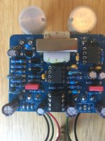
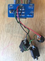
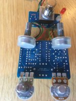
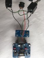
It worked fine for a few weeks after some kind folk here pointed out that I had the daughter board upside down. Unfortunately, the sound started to degrade sporadically and now sounds crappy 100% of the time. I’m pretty sure this pedal should boost the volume way above unity but only manages a little over now and the general tone is raspy, like the signal is spluttering out especially when the gain and treble are set high.

I have not strayed from the parts list provided by Aion, so all components are as per their spec.

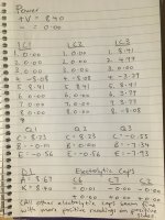
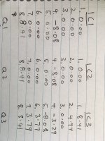
After reflowing all of the joints to no avail, I’ve tried using an audio probe and found the first troublesome component to be R1. On one side of it the signal is fine but on the other, the raspy tone starts. I pulled R1 out, tested it with a multimeter and put it back in as it was fine. I also found that I was getting no signal from a couple of the electrolytic caps whatsoever but I don’t know if this is normal as it’s my first attempt at using an audio probe.

Anyway, I’ll post a pic of the readings I’ve gathered and hopefully some kind clever clogs out there can see what’s going wrong…

Thanks

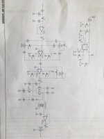
https://aionfx.com/app/files/docs/isotope_documentation.pdf
 

Attachments

  • image.jpg
    image.jpg
    1.4 MB · Views: 15
  • 50C3C52C-C65E-469A-A4D3-95DB1ABE0422.jpeg
    50C3C52C-C65E-469A-A4D3-95DB1ABE0422.jpeg
    1.4 MB · Views: 16
  • Like
Reactions: fig
Your IC voltages are off. I would check the 1044 chip (power) first. For example, pin 5 should have negative voltage, not positive. Are you running this on a battery or wall wart?
I’m running it off wall wart. I’ve tried different adapters (boss and voodoo lab) and power outlets around the house but that doesn’t seem to give any different results.
 
I’ve flipped my numbers around for the IC’s so they are correct now.
It's going to be difficult to provide much help without pictures.
I tried adding pics of the board last night but the images were too large to load. When I went to try again this morning I saw that from all of the handling one of my ground wires has broken.
 

Attachments

  • image.jpg
    image.jpg
    1.5 MB · Views: 23
  • image.jpg
    image.jpg
    1.4 MB · Views: 23
  • image.jpg
    image.jpg
    1.5 MB · Views: 21
The resistor values I can see look good. Polarity for the caps is fine too. Can you confirm the values of the caps? On the solder-side, can you confirm that there isn't a bridge between pins 1 and 2 of IC1?

I also found that I was getting no signal from a couple of the electrolytic caps whatsoever but I don’t know if this is normal as it’s my first attempt at using an audio probe.
The only electrolytic caps in the audio path are C2, C6, and C7, all of the others should not be probed.

Have you retested the circuit after fixing the ground wire issue? Your voltages seem fine. I can't really see all of your wiring, but I'm assuming that the daughterboard is connected properly.

The R1 issue is very strange. The circuit uses a split rail power supply and the audio path is at 0V. The input is AC-coupled to the unity gain op-amp stage. Try probing the circuit again while tracing the audio line presented in the schematic. The signal should be pretty much unaltered compared to the input signal until you get past C2.
 
The resistor values I can see look good. Polarity for the caps is fine too. Can you confirm the values of the caps? On the solder-side, can you confirm that there isn't a bridge between pins 1 and 2 of IC1?


The only electrolytic caps in the audio path are C2, C6, and C7, all of the others should not be probed.

Have you retested the circuit after fixing the ground wire issue? Your voltages seem fine. I can't really see all of your wiring, but I'm assuming that the daughterboard is connected properly.

The R1 issue is very strange. The circuit uses a split rail power supply and the audio path is at 0V. The input is AC-coupled to the unity gain op-amp stage. Try probing the circuit again while tracing the audio line presented in the schematic. The signal should be pretty much unaltered compared to the input signal until you get past C2.
I have double checked resister values and cap values. All caps are as per the build docs. There is a bridge between pins 1 and 2 on IC1. I happen to have a spare board for this project and there is definitely a trace between the two so that shouldn’t be a problem.
 
The resistor values I can see look good. Polarity for the caps is fine too. Can you confirm the values of the caps? On the solder-side, can you confirm that there isn't a bridge between pins 1 and 2 of IC1?


The only electrolytic caps in the audio path are C2, C6, and C7, all of the others should not be probed.

Have you retested the circuit after fixing the ground wire issue? Your voltages seem fine. I can't really see all of your wiring, but I'm assuming that the daughterboard is connected properly.

The R1 issue is very strange. The circuit uses a split rail power supply and the audio path is at 0V. The input is AC-coupled to the unity gain op-amp stage. Try probing the circuit again while tracing the audio line presented in the schematic. The signal should be pretty much unaltered compared to the input signal until you get past C2.
Hopefully this is a better view for wiring.
 

Attachments

  • image.jpg
    image.jpg
    1.3 MB · Views: 13
Like I said, I’m new to using an audio probe and don’t really know what to expect. I was under the impression that as you move through the circuit you will hear components change the signal progressively. What I’m finding here though is that I can hear the whole circuit from the beginning. Even at the input jack I can hear distortion and can alter the sound with the pots. Is this normal?
 

Attachments

  • image.jpg
    image.jpg
    1.2 MB · Views: 8
What I’m finding here though is that I can hear the whole circuit from the beginning. Even at the input jack I can hear distortion and can alter the sound with the pots. Is this normal?
That’s not normal, no. In that picture you’re probing the sleeve of the jack (i.e., the ground); you’ll need to probe the tip to get the signal.
 
Back
Top Bottom