Weird voltages on a twin face Ge side

kurtis1

Member
I built this twin fuzz face from pedal pcb. The silicone side works fine but on the Ge side I can't get less than 8.2v on Q2.


The voltages are wierd all over the Ge side of the circuit. I've tried a different set of ac128 transistors and I get the same results. The voltages after R1 should be 10x what they are. What would cause this? Is C1 somehow dumping voltage to ground? Is that possible? I've attached my voltage readings, a gut shot and a diagram from electrosmash dictating the correct voltages.

Thanks


https://drive.google.com/file/d/11HeCZtQq7UNQSgBajusg15dBdL9xz1_A/view?usp=drivesdk


https://drive.google.com/file/d/11JzXTKd427Umf7C3R2YzHwNdkFP4bMte/view?usp=drivesdk


https://drive.google.com/file/d/11HwKKZ5r85hbMWDtrI2pKyV40K4kqqJr/view?usp=drivesdk
 
Switch up for Silicon, Switch down for Ge!
You should be getting Negative Volts on the PNP side!

Yeah, I definitely am getting negative volts. Sorry I thought that was implied, I should have been more descriptive.
I just think it's so strange that my voltages are all 1/10th of what they should be.
 
Yeah, I definitely am getting negative volts. Sorry I thought that was implied, I should have been more descriptive.
I just think it's so strange that my voltages are all 1/10th of what they should be.
Your Picture isn't Good for checking the resistors.
Here is the Resistor Calculator I use
Click on Bands for 5 :

Has to be a Resistor value or a Bad solder joint!
I'm not a Fan of Transistor sockets!!!

Here's my Build with added Tone control
:https://forum.pedalpcb.com/threads/twin-face.2133/

You said '' GE side I can't get less than 8.2v on Q2''.
And here's my discussion with Crazy Voltages !!!! :
 
Last edited:
Your Picture isn't Good for checking the resistors.
Here is the Resistor Calculator I use
Click on Bands for 5 :

Has to be a Resistor value or a Bad solder joint!
I'm not a Fan of Transistor sockets!!!

Here's my Build with added Tone control
:https://forum.pedalpcb.com/threads/twin-face.2133/

You said '' GE side I can't get less than 8.2v on Q2''.
And here's my discussion with Crazy Voltages !!!! :

I checked all my resistor values, they look good.

Your build looks good, is yours a different version though? I have 2 caps above my ic yours only has one.

I see your discussion. But just basically says "hit the switch" with no replies. my pedal works and plays fairly well and the GE side even sounds kinda alright, but I definitely need to get it biased correctly.
 
Running a jumper wire from lug 4 of the 4pdt switch to lug 3 on the fuzz causes my voltage to be correct. It seems to cause GE Q2 to read at the correct 4.5 - 5v

Wtf? Can someone help me wrap my head around this? What could be causing this?


Edit :I should add that all the other voltages are still nowhere near what they should be when I do this and the issue is not solved
 
Last edited:
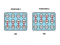
Check for Continuity on the Toggle Switch to make sure only Centre & Bottom or Centre & Top.
If too much heat, you may lose connection!
Position 1 Up
Position 2 Down :
You have to be careful when Soldering any Switch that you don't overheat Pads, 10 to 15 seconds between pads & always stagger, never next to each other !!!

1619306406288.png
 
Check for Continuity on the Toggle Switch to make sure only Centre & Bottom or Centre & Top.
If too much heat, you may lose connection!
Position 1 Up
Position 2 Down :
You have to be careful when Soldering any Switch that you don't overheat Pads, 10 to 15 seconds between pads & always stagger, never next to each other !!!

View attachment 11272
I've checked that switch so many times already. I've bypassed each lug with a jumper wire and still no change in voltage.

I also have checked every lug on the switch for continuity and the switch seems to work perfectly.
 
If you have the Toggle switch Down, what voltage do you have on NPN Q2 Collector.

When toggle is Up, what is the voltage on NPN Q2 Collector?
My 9v electro harmonix wall adapter I'm using is out outing 9.8v at the pedals DC jack.

With the toggle switch down (pnp selected) I have 9.63v on the Q2 NPN collector
-8.7v on the PNP Q2 collector

Toggle switch up (NPN selected) I have 5.2v on the Q2 npn collector.
-9.45v on the PNP Q2 collector


Btw, thank you very much taking the time to think this over. I appreciate you helping me try to understand wtf is going on here.
what happens if you rotate the PNP trimmer completely in the opposite direction with Toggle in PNP Down mode.
If you still have 9.4v to -8.7v, Your trimmer is shot
 
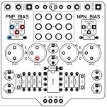
Can you test for Continuity on these matching Circles
If this is Good, Remove your Trimmer & use an offboard 25K TO 50K pot and attach 2 wires to the Pot outside leg & middle leg & attach the wires to the trimmer colours marked Red ( either Red) & Blue
If this dials the Transistor to 4.5v, remove pot without moving pot setting & measure the resistance:

Twin Face ContinuityTest.jpg
 
Last edited:
what happens if you rotate the PNP trimmer completely in the opposite direction with Toggle in PNP Down mode.
If you still have 9.4v to -8.7v, Your trimmer is shot
With my pnp Trimmer a the way down I'm at 8.7v with it all the way up I'm at 9.5v.

Ill desolder this Trimmer and try a different one and report back.
 
Can you test for Continuity on these matching Circles
If this is Good, Remove your Trimmer & use an offboard 25K TO 50K pot and attach 2 wires to the Pot outside leg & middle leg & attach the wires to the trimmer colours marked Red ( either Red) & Blue
If this dials the Transistor to 4.5v, remove pot without moving pot setting & measure the resistance:

View attachment 11277


I take it that this is good? I'm going to hook up another pot and report back

Thanks for your help here!
 
Okay, I hooked up wires to pad 1 and 3 for the trimmer. I then ran those wires to a 100k potentiometer lugs 2 and 3. It took 74.3k of resistance to get that collector on Q2 to read 5v

The voltage on q1 still read the same low numbers as indicated in that first diagram I posted with my voltage readings
After everything said & done, I think you have counterfeit AC128 Transistors, where were they purchased from?
If they ae genuine, you have an issue in the soldering of components on the PNP side.
 
Back
Top