What's the Big Deal with Power Supplies?

Chuck D. Bones

Circuit Wizard
It just makes DC, how hard can that be? Over the course of my engineering career, one of the things I did was design power supplies. The guys who used those power supplies, RF designers, digital designers, precision analog designers, all underestimated the difficulty in designing a power supply that met their requirements. That's assuming they even knew all of their requirements. As pedal users, we want power supplies to (as a minimum):
  1. Provide the correct DC voltage under all conditions:
    1. high line
    2. low line
    3. high load
    4. low load
    5. start up
  2. Be quiet. The DC should have no AC ripple or noise riding on it.
  3. Be stable (not oscillate) over the range of load conditions presented by pedals.
  4. Provide isolation between pedals.
  5. Be reasonably efficient.
  6. Tolerate fault conditions like shorted outputs.
Doing all this is not easy.
Meeting requirement #1 means the power supply must contain regulators. Regulators use feedback to regulate their output voltage and can go unstable with certain loads. Too much capacitance, not enough capacitance, not enough current load can all cause instability. Pedal power supply designers will never know what's inside all of the pedals you might use. They take their best shot.
Requirement #2 means we need filtering, which can also lead to stability issues. Passive filters (inductors and capacitors) are bulky.
Requirement #3 we already talked about.
Requirement #4 means every output should have its own regulator. In the truest sense, isolation means that the grounds are isolated too. Many multiple-output power supplies do not have isolated grounds, they all share a common ground. Only the more expensive power supplies have isolated grounds.
Requirement #5 drives the power supply designer to use a switching regulator. That can be good or bad depending on how good the designer is at doing their job. Switching regulators are harder to stabilize and some of them won't regulate into no load. They also require more filtering and are sensitive to the board layout and routing.
Requirement #6 means the designer has to include current limiting, an electronic circuit-breaker or some other fault management strategy. Fuses are not too convenient.

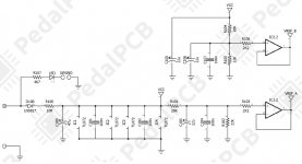
Pedals that have resistor in series with their power input make life much easier for the power supply because there is a smaller surge current when the power supply starts up and has to charge the pedal's filter caps. That resistor also provides some separation between the pedal's filter caps and the regulators, which aids stability. A resistor as small as 10Ω will help.

These days, when I have a pedal with a squealing problem, first thing I check is the power supply. That's because a couple years ago I spent the better part of two days troubleshooting a Vero build only to find out that the Monoprice power supply I was using had gone unstable with that load.
 
Last edited:
Thanks again for the dose of wisdom! So would it be a good idea to include a 10ohm resistor or similar small value on all designs we do or are there downsides to using that? On some designs you see 68 ohm, 100 ohm and stuff? How do the circuit designers determine that or do they pull it out of thin air? Does that resistor also have a bit of a smoothing effect on any residual ripple akin to a choke (or powerfiltering) resistor in tube amp?

Which of the commercial power supplies would you think get a tick by Sir Chuck, get a badge of goodness or suckiness?
How about the SMPS type powersupplies by Truetone, like the CS 12 (which a friend of mine has... ;) ), so far good experience with for what it's worth.
 
  • Like
Reactions: fig
I cut one of my cables and hooked up my scope, is the the proper way to test the ripple?
MlFXxHR.png
 
Yes. You could speed up the sample rate. Switching-Mode Power Supplies (SMPS) produce spikes at the switching freq, or 2x the switching freq depending on the topology. That noise is usually measured as Vp-p or Vrms. It's a tricky measurement because we're looking for small, high-speed AC signal. The cable inductance can magnify the apparent signal.

I have very little personal experience with pedal power supplies, so I cannot recommend one over the other. All of the ones I have are cheap, were made in China, and most of them work ok. I have a couple of stinkers that like to motorboat. My Caline CP-5 is good enough for most pedals, but there are 1 or 2 pedals that make it motorboat.
 
It's defo a big deal when you come to selling, it's amazing the amount of musos that don't have a clue how they affect noise and come back sayin this volcano mega gain pedal's noisy

I'm sure I've bored everyone with this before but I used to demo pedals with a battery, a cheapo made in utter pradesh ronco bronco and a good quality ps just to let people hear the difference in noise
I cannot imagine a serious musician not knowing their gear inside and out, but not everyone thinks like me.....pity, I know.
 
Requirement #4 [provide isolation between pedals] means every output should have its own regulator. In the truest sense, isolation means that the grounds are isolated too. Many multiple-output power supplies do not have isolated grounds, they all share a common ground. Only the more expensive power supplies have isolated grounds.

Hmm, I always assumed that when pedal power supplies are marketed with "isolated outputs", they meant both power and ground were isolated.

Is there any way to isolate both power and ground other than with a transformer?

Several years ago, I thought about designing a pedal power supply. (By "designing", I mean just gluing together off-the-shelf components, not really designing in the sense of actual engineering.) I wanted both power and ground to be isolated and lots of outputs and high-current capability and high-efficiency. The last requirement, high-efficiency, was so that it could be run of AC power or a bunch of 18650 cells.

Unless I'm missing something, meeting that first requirement - power and ground isolation - meant I either had to have a custom transformer made (i.e. with as many secondaries as outputs), or using individual isolation transformers per-output. That alone made cost and/or size blow up right away. So that's when I decided $200 for a quality off-the-shelf pedal power supply wasn't such a bad deal after all... but with the assumption that those OTS PSUs had "truly" isolated outputs (i.e. power and ground). For power isolation only, it's not that hard to make something that's probably decent, like a classic linear power supply (transformer + rectifier + smoothing caps), followed by something like an LM7809 per-output.

Also, if you start with a single DC source (i.e. batteries), and wanted many truly isolated (power + ground) outputs, if transformer(s) is(are) indeed the only way to isolate, then you need an additional inverter step, which certainly doesn't help with efficiency. IIRC, when I was researching this, I did see an OTS IC that would do DC isolation, but I think behind the scenes it was just an inverter + transformer + rectifier; it wasn't cheap and had fairly low current capabilities.

I still think it would be pretty slick to have a pedal PSU that had a modern battery pack (like a laptop battery), complete with "pass-through" charging, so you could run off battery, or run and charge at the same time (like a laptop). I think a few 18650s would keep most boards running for quite a while.
 
The most efficient way to isolate ground is to use a single transformer-isolated DC/DC converter with multiple secondaries. Unless you are prepared to wind your own, that's an expensive proposition as you surmised.

If you don't need too many isolated outputs, then individual power supplies is a low cost option.

Since you brought up battery power, that offers a method of isolation that does not require a transformer. Charge all batteries in tandem, with no ground isolation. Then disconnect the charger, removing the shared ground connection at the same time, and run each effect on a dedicated battery.
 
I know this is old but found it to be an interesting read. I have read through it a few times and never saw a response about the 100r resistor ( or 10r etc..) in series with the power input. In new circuits or layouts is there a reason not to include this resistor?
 
It depends on the power supply current. The voltage drop in that series resistor is governed by Ohm's Law. If the current draw is 1mA, then a 100Ω resistor only drops 100mV which is no big deal. Now consider the Lovepedal Vibronaut. That uses a charge pump to boost the 9V rail up to 17V for powering the lamp. The lamp current can get up to 20 or 30mA. That current is doubled by the charge pump and reflected back to the power source. So now we're talking about 40mA or more flowing thru that 100Ω resistor. A 4V drop is way too much, so we should be using maybe 10Ω in that case. Conversely, in some of the BJFe pedals the current is very low and BJ uses a 1K series resistor for filtering.
 
Okay so I took a look at the Photon Vibe Schematic (pedalpcb vibronaut) and it looks like the power goes through the charge pump (1044 in this case) producing 18v then goes through a 100r resistor and a 100n cap (additional filtering) then goes into the 15v regulator. In this case is that 100r resistor adding the desired effect we are after just doing it after it‘s been ramped up to 18v or am I way off? I am not an engineer so it may be that my brain sees 100r and it happens to be coincidence In this case.
 
You're talking about R29. Like ITCRock said, it's for filtering. But it makes voltage drop in a place where we can't afford any voltage drop. Anyone who has built a Photon Vibe, put a DMM on the output of IC5 (or pin 8 of any of the TL072s). You probably won't see 15V there because a) the charge pump doesn't make 18V, and b) the 78Lxx regulators need a minimum of 3V from input to output in order to regulate. Which is why I recommended using 78L12 instead.
 
Back
Top