Further down the Ge rabbit hole, possible stupid question

MBFX

Well-known member
Hello again everyone! Harvest is nearly over, the vines are dropping their leaves, and I am getting my life back, which means the pedal building will ramp back up. My obsession recently has been making the perfect vintage combo pedal for my favorite tube amp. Through lots of experimentation and parts orders I have narrowed this down to a Ge Fuzz Face into a Ge Rangemaster, a la AnalogMan Sun Lion, into a Ge diode Green Ringer. The combo sounds incredible on my breadboards, has surprisingly low noise, and I am ready to box all three up into a single 1590XX enclosure with three footswitches a la Hoof Reaper. The problem is, The FF and RM need center-negative power, and the GR needs center-positive power. I can't flip the FF and RM circuits due to bad oscillation.

Since I can wire up a PNP FF/RM and power it with a 9V by connecting the power leads backwards, I assume that will work inside a pedal with a power supply. My plan is to use a center-negative power supply, and connect the FF and RM boards to it backwards, so that ground is positive. the GR board will be connected normally.

Is that going to cause some sort of problem I'm not anticipating, since the power will be tapped from a single source instead of separate, isolated supplies? I know electrons don't care which way they are flowing, but maybe someone has tried something like this and knows something I don't. I'm worried about noise or oscillation.
 
Yeah I think that’s definitely a possibility and a charge pump is a good idea. I’m trying to think about what kind of electrical problem you could run into, but I’m no expert here.
 
This is 100% doable.

Ive done this with my Silky Fuzz circuit. I used PNPs and flipped the circuit upside down and flipped the polarity of the Electrolytic caps. I do not like using a charge pump for the simple reason they can be noisy. If youre having problems with noise you can always try a 100pf to 220pf on Q2s base to collector. This might give a little more bass but will ultimately do what you want and thats to reduce noise.


Heres my schem for a PNP based FF without a charge pump....
silky fuzz schem.png
 
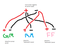
Flipping my Ge FF circuit caused oscillation and flipping the RM caused weird hissing, unfortunately. Both circuits have to have positive-ground power. My question isn't about wiring the circuits themselves though, but rather about powering them from the same source, like so: 1699831842139.png

@Chuck D. Bones , feel like helping me out again..?

Each circuit is discrete, on its own little board. The only functional difference between making three separate pedals and making what I want to make is powering all three circuits from the same tap. It has never been a problem before, but I've never mixed "regular" and "backwards" circuits before.
 
Each circuit is discrete, on its own little board. The only functional difference between making three separate pedals and making what I want to make is powering all three circuits from the same tap. It has never been a problem before, but I've never mixed "regular" and "backwards" circuits before.
That shouldn’t be a problem… I think there something might be wrong with your wiring…

The power supply is giving 9volts regardless how the circuit is wired. Have you tried wiring it normally?
 
That shouldn’t be a problem… I think there something might be wrong with your wiring…

The power supply is giving 9volts regardless how the circuit is wired. Have you tried wiring it normally?

Well, I haven't stuck any of these in the box yet. I would like to avoid too much rework so I came here to consult the oracle, so to speak. Perhaps I am explaining my intent poorly... please bear with me.

Imagine a positive ground Fuzz Face, a positive ground Rangemaster, and a negative ground Green Ringer. Three separate pedals, all in their own boxes with a DC jack. You want to power all of them, but you can only use a single power outlet to do so. You can't use a daisy chain to power them, because it won't give the correct power to all the pedals. For our purposes, batteries are not an option; you must use the wall outlet and you only get one of them.

My solution to this thought experiment is to modify my daisy chain, so that there are three positive leads and three negative leads. The leads going to the Fuzz Face and the Rangemaster are flipped, so positive is connected to ground. That gives those two circuits -9VDC, while the Green Ringer still gets +9VDC. The only connection between them, other than the audio signal connections which are separated by DC filter caps, are the common power source. Will that common power source cause problems?
This is gonna sound like a nitpick but it would be more clear if you used the term positive power rail and negative power rail. Ground is always at 0V which is neither negative nor positive, so applying the terminology to it may be confusing.
 
This is gonna sound like a nitpick but it would be more clear if you used the term positive power rail and negative power rail. Ground is always at 0V which is neither negative nor positive, so applying the terminology to it may be confusing.

May I please have more context?
 
May I please have more context?
Ground is conventionally defined as the reference against which we measure all voltage. This comes out of the physics of electromagnetic fields: voltage only has meaning compared to some reference (in other words, the voltage difference between two points is what determines the EM field and forces between the two points). That reference is ground in electrical circuit, which in practice is identified with a very large conductor, the whole earth (thus the name - I cannot remember why it’s defined this way). Circuits are usually designed with this key assumption in mind. Now your voltage can be either positive or negative with respect to ground (again, never in absolute!). The sign merely determines the direction of the electrical field, but when it comes to discrete electronics the polarity of the field is important to the way semiconductors work (transistors first and foremost). The most common circuit designs for NPN transistors use positive voltage for biasing. PNP ones work exactly opposite to that, so if you apply a circuit designed for NPN to a PNP transistor, you can use it unchanged (mostly, you may need to adapt to the frequency response of the transistor) simply by using negative voltage to bias the transistors instead of positive.

Now if you have an isolated power supply, you can power a PNP circuit by applying the positive voltage pin to the ground lead, and the negative voltage pin to the power lead (notice that such supplies don’t usually indicate the negative pin as ground). That means the relative voltage between power and ground will be negative (say -9V). This should work fine because the negative lead is not actually “ground” in the general sense (not literally connected to earth). If it were, I think you would pick up a lot of noise from ground. I think when you try to power a circuit that requires positive power with the same supply as one that requires a negative one, you may be introducing a lot of noise to the power rail (the ground of one will affect the noise for the power in the other and vice versa), which is what you’re hearing. Somebody like Chuck can give a much more thorough and scientific explanation than mine (my EE skills are OK but very very rusty and out of practice).

Edit: I think about ground as the garbage bin of EM signals…
 
Last edited:
Seems like to me without seeing how you're actually connecting these together on the audio side but by using a single power supply it would probably conflict because some having positive on the ground and some having negative on the ground you may short out your transformer because the audio cables connecting the sleeve on them is expecting well negative to be the sleeve and tip to be audio signal so if your power supply is common between this pedal and another one could possibly conflict because of the common connection if this is the only pedal that's being used maybe it's not a problem.

So you have tried making the two petals that use positive ground with NPN transistors in reversing your polarized caps?
 
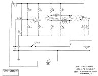
It seems like the simplest (as well as most historically accurate) solution would be to build a "positive ground" (or "negative power rail") version of the Green Ringer. Many (most?) of the original Dan Armstrong units were built that way (as per the 1975 DA schematic below). Use two of your PNP transistors of choice for Q1 and Q3, and an NPN for Q2, and reverse the diodes and any electrolytic or tantalum caps. It probably wouldn't be too hard to match the sound of your currently breadboarded "negative ground"/"positive power rail" version.
dagreenringer.jpg
.
 
Dude this is EXACTLY what I needed! I have 3 AC128s that just aren't doing it for me in a Fuzz Face - too clean. I'll drop them in this! The AC128s are around 60hfe. What do you recommend for the NPN, something higher gain? 2N5089?
 
As far as dropping in germanium into Q1 and Q3, I've not done it myself, but I expect you might need to diddle R1 and R2 slightly (part numbers as per the DA schemo) to account for leakage. Q3 is essentially a output buffer stage, so it may work as it is. Other, greater minds than mine (and any would be greater!) would know. But it's certainly worth a try.

As far as hFE for Q2 (and for the others for that matter), I've found it not too fussy — the 2SC828s that Armstrong used were often on the lower side (I think I've seen pics of 2SC828-Rs primarily, which generally run from around 180 to 360). If the AC128s don't work out for you, you can probably get a decent result from 2N3906s or 2N5087s for the PNPs and a 2N3904 or a 2N5088 for Q2. YMMV, as always, but I put together an excellent one with one 2N3707 and two 2N4058s, and all of those were around or under 225 hFE.
 
I have some NOS Motorola 2N5087s that I bought for my Squidward PCB... maybe I should just use those, and save the AC128s for Rangemasters or something. Maybe I'll make a Darlington pair Rangemaster and kick my preamp in the dick with signal
 
You jest, Shirley (don't call me, surely), but I did make a Ge Darlington boost for bass (basically it was Rangemaster topography but with much larger input and output caps and heavily low-passed at the input), stuck a pair of clipping diodes at the end, and it made the most godawful Jack Bruce/Felix Pappalardi/Mel Schacher-type of blowing-up-the-amp tone. 'Twas glorious. :LOL:
 
Back
Top