SOLVED LED Dimly Lit In Bypass

Ginsly

Well-known member
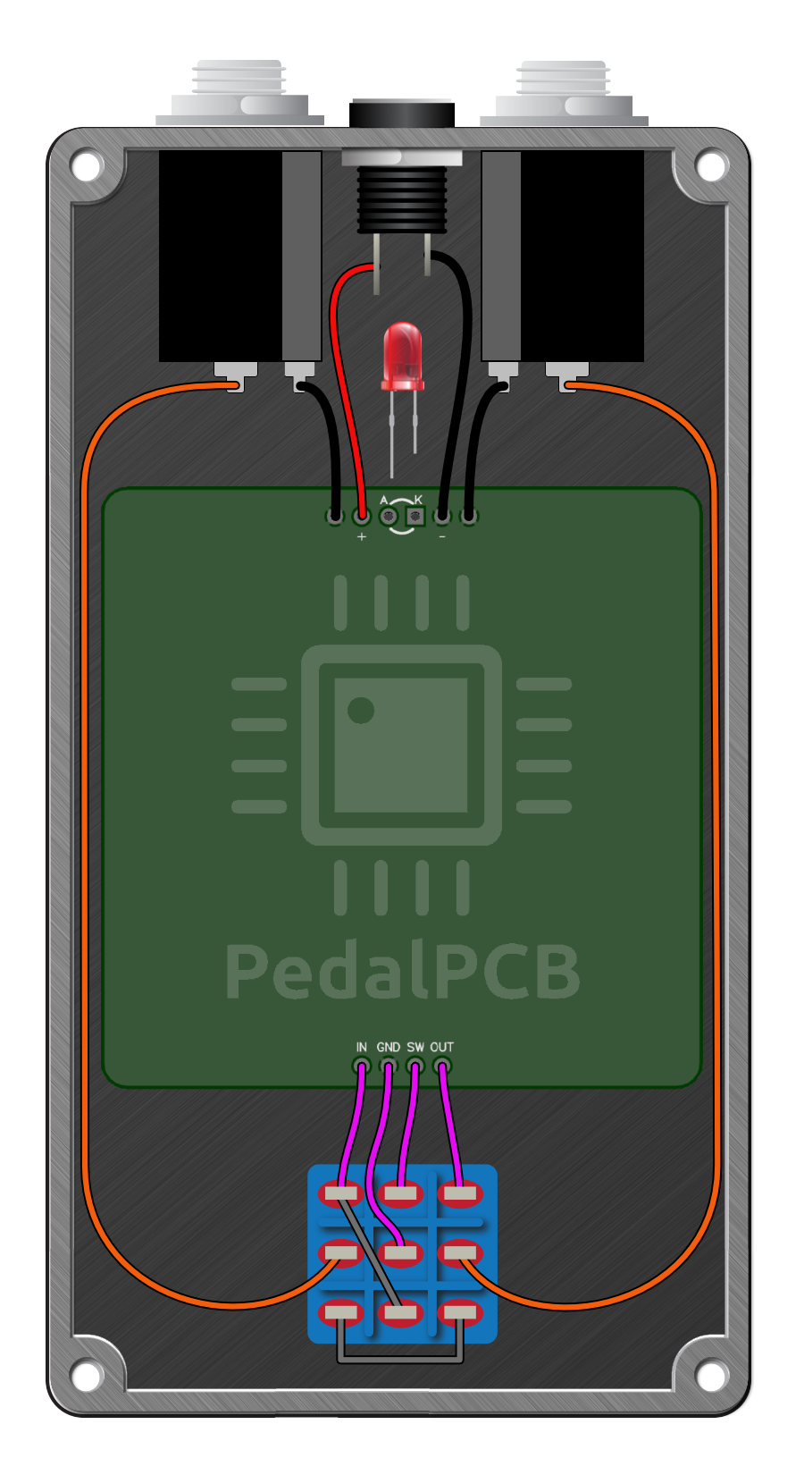
Are there any “most likely” reasons for this? I just put together a PPCB-style fuzz board (Fig Buster - thx @KR Sound!) and I’m having this problem. I did add a battery snap, and that’s how it’s powered. I also used a PPCB footswitch pcb.

Pedal seems to work normally other than the LED staying VERY dimly lit when in bypass. I repurposed an old enclosure and used off-board pots because of that. Also added some screw terminals, which I think over complicates things 🤦‍♂️. No solder bridges that I can see…

I’m away but will add pics later- apologies. Just wanted to see if there were certain things to look at when this happens. Much appreciated!
 
Last edited:
I had this exact same problem last year. After eliminating all possible problems with power, ground, switches, etc. it turned out that particular batch of blue LEDs I bought were the issue (I was able to reproduce the problem another way).

IIRC, jimilee had the same issue with a different set of blue ones. Maybe we bought them from the same source.
Self-grounding LEDs? Must come with extra pixies.
 
Thanks everybody, I really appreciate it!

@jwin615 huh, I didn’t consider that. All parts other than the enclosure are new, but I did indeed use a heat gun on most of them to shrink tubing- including on the DC jack and LED itself. Low setting, but still.

@Robert @VanWhy @KR Sound @eh là bas ma I used the basic 6-pad PedalPCB footswitch pcb. I tested continuity on the 3pdt itself and it seems like the switch isn’t fried or anything. Everything seems to function normally except for this.

I attached headers to the 3pdt pcb, and I plan on removing them- could be a solder bridge underneath I suppose. Robert, I’ll have to check the Vol control/brightness situation- I assume you mean in bypass.

@bean Ahhhh that’s very, very good to know. Changing the LED is a pretty easy first step, I’ll look at that for sure. Sounds like quite the frustrating situation when it happened to you- sorry to hear that! I’m using the same batch I’ve used before without issue, but ya never know. I did hit this one with a heat gun after all…
I totally misread or other wise wholely miscomprehend your issue. DC jack is likely fine.
Words is hard.
 
Thanks everybody, I really appreciate it!

@jwin615 huh, I didn’t consider that. All parts other than the enclosure are new, but I did indeed use a heat gun on most of them to shrink tubing- including on the DC jack and LED itself. Low setting, but still.

@Robert @VanWhy @KR Sound @eh là bas ma I used the basic 6-pad PedalPCB footswitch pcb. I tested continuity on the 3pdt itself and it seems like the switch isn’t fried or anything. Everything seems to function normally except for this.

I attached headers to the 3pdt pcb, and I plan on removing them- could be a solder bridge underneath I suppose. Robert, I’ll have to check the Vol control/brightness situation- I assume you mean in bypass.

@bean Ahhhh that’s very, very good to know. Changing the LED is a pretty easy first step, I’ll look at that for sure. Sounds like quite the frustrating situation when it happened to you- sorry to hear that! I’m using the same batch I’ve used before without issue, but ya never know. I did hit this one with a heat gun after all…
Sheeeiiitt you don’t know the half of it. I threw away a whole new batch of stomp boards because of it.
 
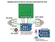
Jumping into this later today, I REALLY appreciate all of the feedback. I'll replace the LED and probably swap the footswitch too. I have a question about that, though. I have these 3PDT boards (see pic) that I love using with stripboard, and I'd like to try one if I have to replace the footswitch on this pedal (ran out of PPCB footswitch pcbs sadly). Can I use these with a PedalPCB-type board?

In order to port the CLR and LED to the 3pdt pcb it sounds like I'd jumper those pads on the main pcb. Other than that, I'm a little confused since the connection pads on a PPCB board are a little different than the pads on these 3pdt pcbs. Do I leave the "SW" pad on the main pcb open, or do I connect that to "L" (led) on the 3pdt pcb?
Screen Shot 2024-02-16 at 11.35.23 AM.png
I connect DC power and both I/O jacks to these when working with Stripboard too, but again, I'm not sure if that's an option with PPCB boards (and what would connect where). I'd love some advice, this will help a LOT in the future.
 
L connects to SW, and you’re right about the jumper.
Gotcha - so even if the CLR and LED are on the 3pdt board, I'll still need to connect SW from the main pcb to L on the FS pcb?

What about the DC jack and I/O jacks? If I use the fs pcb for both of those, I'd:

- connect Sleeve and Tip from the I/O jacks to the designated pads on the fs pcb. Leave the Sleeve Ground pads at the top of the main pcb open?
- connect the DC jack to the designated pads on the fs pcb. Do I leave the + and - on the main pcb open? Or do I connect THOSE to "9v" and "G" on the fs pcb instead of the pads at the bottom of the main pcb as usual? Or do I have to connect the DC Jack directly to the main pcb?

This probably has a very clear answer, but I'm a really confused beginner right now...
 
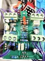
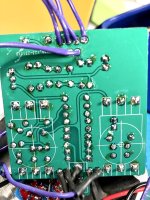
Update: redid a bunch of wiring, tried a different 3pdt switch, new LED, no change. I’m at a loss. These are atrocious since I did some desoldering, but here goes. Those are screw terminals I used to hook up the pots. Actually wound up being helpful with all of the back and forth!
IMG_1381.jpeg
IMG_1382.jpeg
 
Back
Top