Green Sreamer

JimL

Member
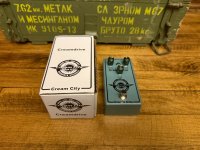
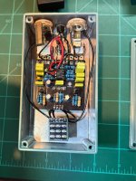
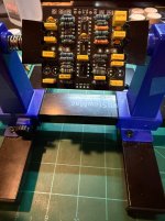
I built a Little Green Screamer. It was an easy build and it sounds ok. It has N4148s in it. Any ideas on how I can mod this pedal to my desire? I bought five boards so I can try mods. My favorite ODs are Wampler Belle and MXR Timmy.
 

Attachments

  • IMG_9288.jpeg
    IMG_9288.jpeg
    404 KB · Views: 30
  • IMG_9287.jpeg
    IMG_9287.jpeg
    474.6 KB · Views: 30
The Tubescreamer is bit different than the Timmy. TS has a mid eq hump where the Timmy is a "transparent" overdrive.

Also, socket things like the diodes, try some LED, LED and 4148, bat41 or even just 1 diode.
 
The Tubescreamer is bit different than the Timmy. TS has a mid eq hump where the Timmy is a "transparent" overdrive.

Also, socket things like the diodes, try some LED, LED and 4148, bat41 or even just 1 diode.
Thanks. I think that I have no understanding of why I would want a glowing led inside my case. The socket idea is a good one. I have to look into what a bat41 is. I know very little.
 
Thanks. I think that I have no understanding of why I would want a glowing led inside my case. The socket idea is a good one. I have to look into what a bat41 is. I know very little.
LED stands for Light Emitting Diode. It works like a clipping diode similar to a 1N4148 but with a higher forward voltage, which changes how the signal clips. Lots of pedals use LEDs for clipping RAT circuits, the JHS Morning Glory and one of my favorites the Keeley Electronics Seeing Eye mod for the Boss DS-1. In that mod, the LED is actually mounted on the outside of the pedal, inside the “O” of Tone on the enclosure. When you play, it lights up in real time you can literally see the signal clipping.
 
LED stands for Light Emitting Diode. It works like a clipping diode similar to a 1N4148 but with a higher forward voltage, which changes how the signal clips. Lots of pedals use LEDs for clipping RAT circuits, the JHS Morning Glory and one of my favorites the Keeley Electronics Seeing Eye mod for the Boss DS-1. In that mod, the LED is actually mounted on the outside of the pedal, inside the “O” of Tone on the enclosure. When you play, it lights up in real time you can literally see the signal clipping.
Thanks for the reply. I still screw up quite a bit, unforced errors. Troubleshooting is not my strong suit yet. I’m gonna get myself some of those BAT41 diodes maybe you could tell me where I could find a socket?
 
Lots of nice articles on this site.

For more lows, you could increase C4. (Also described in the Wampler article MOD 3).

Reading the electro-smash tube screamer article several times can go a long way.
 
More low end is straightforward. If you use the PPCB schematic, make C4 bigger. R8 and C4 make a high-pass filter which is what gives the TS that mid-hump. Making C4 bigger will move that mid hump down in frequency. Try 100nF and go from there.

I would consider using more clipping diodes to make the sound less compressed. It's surprising how using two pairs of 1N4148s instead of just a pair opens up the feel. So where D1 and D2 are use a pair, like this:

Screenshot 2026-01-19 at 9.28.28 am.png
 
Thanks! I appreciate it. I am very uneducated in electronics but I understand your diode idea, I will try this along with the 100n. Also d1 and d2 have the negative on the same sde I believe because of the led inside the footbrint
 
Last edited:
Thanks! I appreciate it. I am very uneducated in electronics but I understand your diode idea, I will try this along with the 100n. Also d1 and d2 have the negative on the same sde I believe because of the led inside the footbrint
Yes, D1 and D2 have the negative on the same side on the PCB. Electrically they're going the opposite directions though, and you can even see the trace go from one's anode to the other's cathode in the picture on the site https://www.pedalpcb.com/product/lgsm/.

Nevertheless, just orient the diodes the same way they are on the board, but instead of using just one, use two in series (if you want to double them up).
 
I once built a Tubescreamer with the 4 diodes as I showed above and added a simple bass pot section where R8 and C4 are. I was amazed at how much better it sounded (to me) than a standard Tubescreamer.

Then you discover that you can build a TS without the buffers. Then you fiddle about a bit more and you realise you have fallen into the overdrive abyss and no one ever sees you again.
 
More low end is straightforward. If you use the PPCB schematic, make C4 bigger. R8 and C4 make a high-pass filter which is what gives the TS that mid-hump. Making C4 bigger will move that mid hump down in frequency. Try 100nF and go from there.

I would consider using more clipping diodes to make the sound less compressed. It's surprising how using two pairs of 1N4148s instead of just a pair opens up the feel. So where D1 and D2 are use a pair, like this:

View attachment 109620

Like this lol? I bought this for $30 off reverb. Basically just paid for the sides lol.

IMG_2472.jpeg
 
Back
Top