CheapSuitG
The TubeSchemer
They will light up, yes.
Socket them and see what you like.
Socket them and see what you like.
I'm trying to understand more about what gives certain pedals their freq response.

Oh geez, I didn't know that and it really helps me understand why simple low- and high-pass filters work, not just how they work in practice. Thank you!So pretty much any of the filters, you can puzzle out what it does by considering that a capacitor lets highs right through and resists lows, and thinking of how that affects the gain.
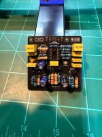
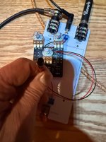
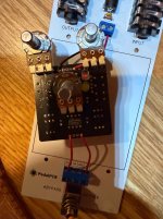
Hey, putting together a new build right now. I’ve already substituted a 100N for C4. I put two.N4148s together in one spot and then the other spot. I’m gonna use one. N4148 for the outside holes and I put a red LED on the inside so that there’s a combination Of the two. Hopefully this works. I probably won’t have it assembled for a bit, but I might be able to put it on the auditorium platform tonight.A lot of it comes down to:
-high frequencies go right through a capacitor, almost as if it was a short.
-low frequencies see a capacitor as a high resistance. The larger the capacitor, the lower the frequencies it “lets through”.
In a non inverting op amp, the gain is set by:
G = 1 + R2/R1
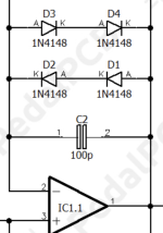
View attachment 109972
(Image from electro smash tube screamer article)
In the case of the tube screamer, the combination "impedance" of C4 and R8 will act as "R1" from the image above. (Impedance means resistance that can change over frequency). Low frequencies will see C4 as high resistance, making "R1" higher, which makes the gain lower. High frequencies will see C4 as low resistance, so "R1" is lower, so the gain is higher. The frequency where lows start to noticeably reduce depends on the equation f=1/(2piRC) where R is R8, and C is C4. This is the same equation as for C5 and R9, even though it is a different arrangement.
For C3, highs use it to bypass the gain pot, so that the equivalent "R2" is lower. So lower gain, so highs are attenuated. Low frequencies are resisted by C3 so the equivalent "R2" is higher.
So pretty much any of the filters, you can puzzle out what it does by considering that a capacitor lets highs right through and resists lows, and thinking of how that affects the gain.
Options for study are:
-read all the articles you can on electro-smash or geo-fx (technology of the...) or similar sites, so you recognize the different filter types.
-model in Lt spice
-experiment on the breadboard.
A combination of all three is best…
The Distortr tone circuit is the same arrangement as a Big Muff tone control. As the treble turns up, lows go down, and vice versa, like a see-saw. Big muff tone controls also tend to scoop out the midrange. I put the Distrotr values into "TSC-in-the-web" on the Big Muff tab, and it actually doesn't look like it scoops mids very much, but the see-saw action remains. It may not be the best tone stack for you, maybe you like a simpler adjustable low-pass like on the Timmy circuit. Ironically, the Amber OD uses that same big-muff style tone stack, but that 1M resistor (R19) makes it hardly cut any bass, so it basically just acts as a low-pass filter. The Luxury is a really similar circuit to the Timmy, though some values are different so it won't sound identical, but it has that simple low-pass tone control.
Oh thanks so much for that. Is there a reason why the light doesn’t light up? I turned it all the way up put the game up but no light. I played it pretty hard, but I get no light.Nice. If you want 2 diodes to change the clipping threshold, you have to put 2 in series (same direction). (Looks like you have 2 diodes same direction in parallel? But for diodes that means it will function just like one diode.
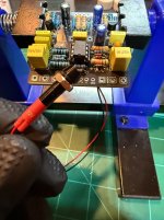
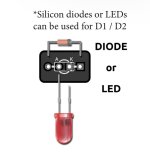
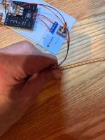
Common way is to build a “tent” to put them in series.
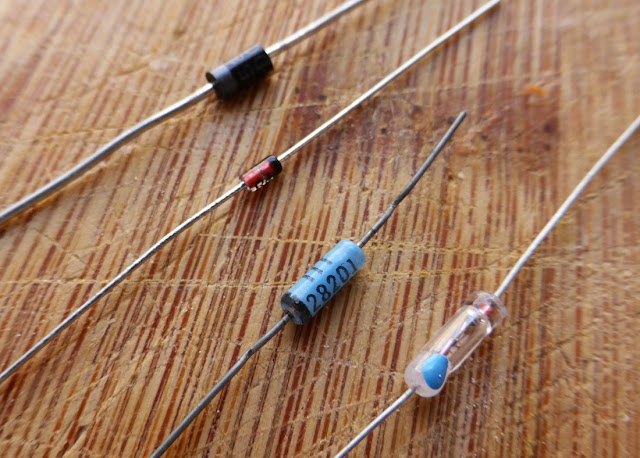
Here’s a nice article on diodes
Coda Effects: The different types of diodes
Learn more about electric guitar related electronics: DIY guitar pedals, from fuzz faces to delays and reverb, cables and circuits theorywww.coda-effects.com
Interesting so I guess I gotta remove these diodes and make them opposites?. I thought I was following this diagram that another member posted.Is the led in the opposition orientation from the 1n4148?
LED has a higher forward voltage (threshold before it clips). If they’re the same orientation, then the 1n4148 will clip before the signal hits the led threshold.
Otherwise, it could be just not enough gain for the led. but I think TS should be able to clip it.
I did try that and I tried several different bulbs that are good. It won’t clip it won’t light up.You could just try swapping the led wires to change the orientation of the led and see if it’s lighting.
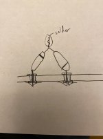
This shows the case where the 1n4148 and led are pointing opposite directions.
So then, instead of mixing N4148 with an LED I should just have two LEDs?This picture how you have it?
The build doc says diode OR LEDs looks like you have both in that spot
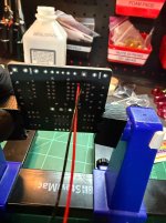
Phil I can’t tell you how much I appreciate it. I removed all of the N414 eights. Looks like now the red bulb does light up. I put a different color in the other one which is orange and that one does not light up.This picture how you have it?
The build doc says diode OR LEDs looks like you have both in that spot
Well, that worked! You are a lifesaver. I appreciate you so much. It might be something simple for you, but it’s like calculus for me and I can’t even do algebra.This picture how you have it?
The build doc says diode OR LEDs looks like you have both in that spot
Thanks again. So what I did is I removed all the N4148 diodes then I just put one red LED. In one slot and I put one red LED in the other slot.. Both lights light up. There’s still a good level of distortion and actually the pedal sounds a little more airy. Probably that C4 increase on the capacitor helped. But this light thing was maddening so I thank you again.Cool! You can still do red led one direction, 1n4148 the other direction, that’s just not how you had it when you had a total of 3 1n4148s. You can just put a 1n4148 back where you were gonna put the orange, try both directions so the red still works.
The orange led should have worked, IF it was opposite orientation of the red.