Fingolfen
Well-known member
Here's the draft version of the Tayda UV Printing Tutorial I've put together. Please provide feedback and then I'll get a final version zipped up as a PDF.
There's also a version on my blog - link will be at the end of the final part of the tutorial.
Steggo Studios Tayda UV Printing Tutorial
This guide is designed for individuals wanting to create enclosures using Tayda Electronics’ (https://www.taydaelectronics.com/) UV printing service using Adobe Illustrator. At this point, Illustrator is the only program that is known to work correctly 100% of the time with the Roland VersaWorks printers used by Tayda. This tutorial will assume that you have a basic working knowledge of how to use Illustrator, but I’ll include a few fun tips and techniques as well.
Step 1 – Start with the Right Template!
Tayda has both Adobe Illustrator and PDF versions of their UV templates. Each size of enclosure has its own template, and they’re available online when you order the UV print job:
https://www.taydaelectronics.com/hardware/enclosures/enclosure-uv-printing-service.html

When you bring the template in to Illustrator, it should have a total of 3 layers: White, Color, and Gloss. Anything that will be printed white goes in the white layer. Anything that will be printed in color goes in the color layer. Any gloss or matte features (even an overall gloss or matte) will go in the gloss layer.
The template itself will be a white workboard in the middle of the screen. These are the limits of your art. Anything outside that area will not print (and may even cause issues with the UV printing process, but I’ve never tried it). I tend to keep my art a bit inside that border as the corners of most of the enclosures sold by Tayda are rounded, not square.
Step 2 – Use your drill template to lay out the enclosure
Just about every commercially available pedal PCB has a drill template available. The first thing you’ll need to do is make sure you have a version of it that is the actual size of the enclosure itself. I typically bring the template into Photoshop, but any photo editing / image editing software where you can adjust the scale of a drawing to real scale should work.
Enclosure sizes can be found in a variety of places:

Once the enclosure has been sized properly, if there is no indication of center on the enclosure, I tend to add some marking (see the “plus” sign in the drawing above) to the center of the template. This makes it easier to center and align the template when I move it to Illustrator, and it allows me to measure the hole locations in Photoshop and create an accurate drill template in the Tayda Drill Tool. I move all of the measurements to Excel and I have a template set up which will generate the numbers I add to the drill tool.

The calculations in the yellow columns are the raw numbers, the ones in the green are rounded with an allowance added for powder coating.
Once the drill template is ready, I move it over to Illustrator and put it at the bottom of the white layer. If you have a blank template, Illustrator should indicate when the drill template image is centered in the workspace.

Step 3 – Add guides to center knobs, controls, and indicators
Just about every pedal is going to have multiple controls on the face of the enclosure – be they knobs, switches, or indicator lights / LEDs. I create guides that allow me to line up each of those features – usually in the white layer. It really doesn’t matter what layer the guides are in, just as long as they are clear and are aligned to where the controls are going to be on the final pedal.

Step 4 – Add representative shapes for the knobs, switches, etc.
At this point you’ll need to make some decisions about what the pedal is going to look like once it is finished. In order to have art that doesn’t end up in the middle of a switch or under a knob, you’ll need to block out space for all the controls. Illustrator is very good about providing the actual size of any feature added to the workspace, so if you have 15mm knobs, then you can create a 15mm circle using the ellipse tool to block that space on the workboard. It is also a handy tool to understand whether or not that 28mm chicken head knob you’d like to use is actually going to work, or if it is going to run over the edge of the enclosure and/or interfere with the neighboring 28mm chicken head knob!

While these knob indicators started out in the “white” layer, ultimately they will need to be toward the top of the color layer (unless you’re doing an enclosure all in white).
Step 5 – Make sure all your art is in vector format
I use a lot of licensed stock art in making my pedals, but I’ve also paid for original art as well. Regardless of the source of the art, all of it will need to be in vector (rather than raster) format to be used on the enclosure. That means anything that is a .jpg, .gif, .png, etc. is going to need to be converted to a vector before it will print.
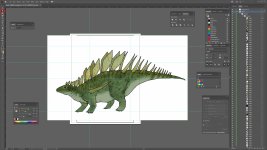
For this enclosure I brought over Clark, the Kentrosaurus, from another program. He’s a licensed piece of art, but as you can see he came in as an image – that’s because Clark’s a .jpg, not a vector. No problem, Illustrator can perform the conversion!

Using the Image Trace tool (which you can see at the bottom right) you can convert the image file to a vector. There are several different modes – I tend to use either “Low Fidelity Photo” or “High Fidelity Photo” the most, though depending on the art, there are lots of other settings that may make sense. Fortunately, you can experiment until you get the result you want!
Step 6 – Expand and edit your image trace
Once the image trace is complete, you’ll need to “Expand” the object. This will split the vector up into its paths and fills, which can then be easily edited.

Once the image is expanded, it should be a “Group” and you’ll be able to edit individual paths in it. This will let you get rid of all of the white space and only be left with the actual image itself (with no background)

Step 7 – Size and place the image
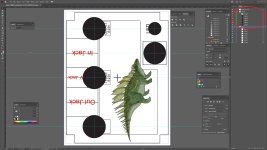
Now that the image is in vector format and any background has been removed, it can be rotated and adjusted to fit the enclosure itself. Because of the orientation of this enclosure, everything must be rotated 90 degrees so that it prints and drills correctly. Also note, at this point I’ve brought everything up to the color layer as this enclosure will have (at least) color and white (more on that later!).

(Continued in Part 2 due to file attachment limitations)
There's also a version on my blog - link will be at the end of the final part of the tutorial.
Steggo Studios Tayda UV Printing Tutorial
This guide is designed for individuals wanting to create enclosures using Tayda Electronics’ (https://www.taydaelectronics.com/) UV printing service using Adobe Illustrator. At this point, Illustrator is the only program that is known to work correctly 100% of the time with the Roland VersaWorks printers used by Tayda. This tutorial will assume that you have a basic working knowledge of how to use Illustrator, but I’ll include a few fun tips and techniques as well.
Step 1 – Start with the Right Template!
Tayda has both Adobe Illustrator and PDF versions of their UV templates. Each size of enclosure has its own template, and they’re available online when you order the UV print job:
https://www.taydaelectronics.com/hardware/enclosures/enclosure-uv-printing-service.html
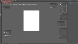
When you bring the template in to Illustrator, it should have a total of 3 layers: White, Color, and Gloss. Anything that will be printed white goes in the white layer. Anything that will be printed in color goes in the color layer. Any gloss or matte features (even an overall gloss or matte) will go in the gloss layer.
The template itself will be a white workboard in the middle of the screen. These are the limits of your art. Anything outside that area will not print (and may even cause issues with the UV printing process, but I’ve never tried it). I tend to keep my art a bit inside that border as the corners of most of the enclosures sold by Tayda are rounded, not square.
Step 2 – Use your drill template to lay out the enclosure
Just about every commercially available pedal PCB has a drill template available. The first thing you’ll need to do is make sure you have a version of it that is the actual size of the enclosure itself. I typically bring the template into Photoshop, but any photo editing / image editing software where you can adjust the scale of a drawing to real scale should work.
Enclosure sizes can be found in a variety of places:
- Tayda has the sizes in mm on their website in the listing of each enclosure type
- Amplified Parts has a list of enclosure sizes:
- Pedal Parts Plus has several templates that give exact dimensions in their “Customize an Enclosure” section:
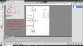
Once the enclosure has been sized properly, if there is no indication of center on the enclosure, I tend to add some marking (see the “plus” sign in the drawing above) to the center of the template. This makes it easier to center and align the template when I move it to Illustrator, and it allows me to measure the hole locations in Photoshop and create an accurate drill template in the Tayda Drill Tool. I move all of the measurements to Excel and I have a template set up which will generate the numbers I add to the drill tool.
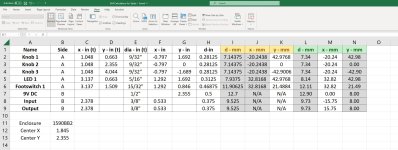
The calculations in the yellow columns are the raw numbers, the ones in the green are rounded with an allowance added for powder coating.
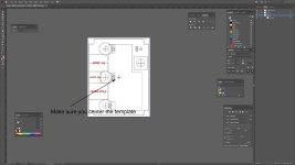
Once the drill template is ready, I move it over to Illustrator and put it at the bottom of the white layer. If you have a blank template, Illustrator should indicate when the drill template image is centered in the workspace.
Step 3 – Add guides to center knobs, controls, and indicators
Just about every pedal is going to have multiple controls on the face of the enclosure – be they knobs, switches, or indicator lights / LEDs. I create guides that allow me to line up each of those features – usually in the white layer. It really doesn’t matter what layer the guides are in, just as long as they are clear and are aligned to where the controls are going to be on the final pedal.
Step 4 – Add representative shapes for the knobs, switches, etc.
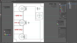
At this point you’ll need to make some decisions about what the pedal is going to look like once it is finished. In order to have art that doesn’t end up in the middle of a switch or under a knob, you’ll need to block out space for all the controls. Illustrator is very good about providing the actual size of any feature added to the workspace, so if you have 15mm knobs, then you can create a 15mm circle using the ellipse tool to block that space on the workboard. It is also a handy tool to understand whether or not that 28mm chicken head knob you’d like to use is actually going to work, or if it is going to run over the edge of the enclosure and/or interfere with the neighboring 28mm chicken head knob!
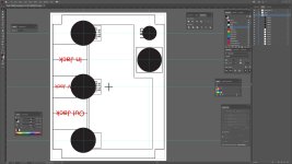
While these knob indicators started out in the “white” layer, ultimately they will need to be toward the top of the color layer (unless you’re doing an enclosure all in white).
Step 5 – Make sure all your art is in vector format
I use a lot of licensed stock art in making my pedals, but I’ve also paid for original art as well. Regardless of the source of the art, all of it will need to be in vector (rather than raster) format to be used on the enclosure. That means anything that is a .jpg, .gif, .png, etc. is going to need to be converted to a vector before it will print.
For this enclosure I brought over Clark, the Kentrosaurus, from another program. He’s a licensed piece of art, but as you can see he came in as an image – that’s because Clark’s a .jpg, not a vector. No problem, Illustrator can perform the conversion!
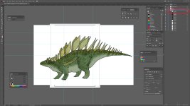
Using the Image Trace tool (which you can see at the bottom right) you can convert the image file to a vector. There are several different modes – I tend to use either “Low Fidelity Photo” or “High Fidelity Photo” the most, though depending on the art, there are lots of other settings that may make sense. Fortunately, you can experiment until you get the result you want!
Step 6 – Expand and edit your image trace
Once the image trace is complete, you’ll need to “Expand” the object. This will split the vector up into its paths and fills, which can then be easily edited.
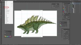
Once the image is expanded, it should be a “Group” and you’ll be able to edit individual paths in it. This will let you get rid of all of the white space and only be left with the actual image itself (with no background)
Step 7 – Size and place the image
Now that the image is in vector format and any background has been removed, it can be rotated and adjusted to fit the enclosure itself. Because of the orientation of this enclosure, everything must be rotated 90 degrees so that it prints and drills correctly. Also note, at this point I’ve brought everything up to the color layer as this enclosure will have (at least) color and white (more on that later!).
(Continued in Part 2 due to file attachment limitations)

