SOLVED All my LED's only work backwards

eliosvanpizza

New member
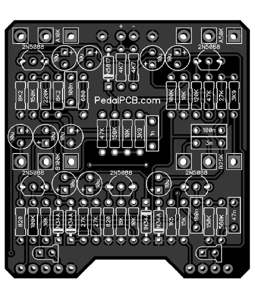
Hello, I've built a Kliche Mini (success) Muffler Noise Gate (failure) and a Cobalt Drive (success).

for all three of those pedals, the LED only works when I reverse the leads- they work with the long lead through the circle and the short lead through the square.

I am following the wiring diagram exactly as written in the build information, but I noticed that my 9V jacks are kinda inverted from what is showed on the diagram. in the diagram the center lug of the jack is positioned higher than the left lug where the positive wire goes. On my jacks, the left lug is positioned higher and the center lug is lower.

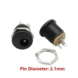
Could this be why my LED's are backwards? These are the 9V input jacks I am using SKU# A-2237 on Tayda

 
Have to agree with @Harry Klippton

I would sacrifice the LED and clip off the legs. I would cut them closest to the body of the LED that way you something to grab with your needle nose tweezers. Then come in from the other side with your solder iron and desolder the joint and pull out the legs. Then use a solder sucker to suck out the remaining solder.
 
The LED markings are backwards for these boards.

Technically they're backwards for most every other DIY effects PCB.... I think this stems from the fact that most guitar effects PCB designers are using a derivation of the old Gaussmarkov Eagle libraries (Madbean, Rullywow, etc) which have the incorrect pinout.

Fire up your PCB layout software of choice and place an LED from the softwares STANDARD component library (not a 3rd party library that has been downloaded/add from some online source) and check out the pinout.


The round pad is the anode, which is the longer lead.

DipTrace
1678642561938.png

KiCad (although it doesn't look like it by the color scheme, the round pad is the Anode here as well)
1678642935789.png

1678643833842.png

Think about it for a moment... the round pad is the anode for every other diode on the PCB (Schottky, zener, etc), why would a Light Emitting Diode be any different?

The round pad for anode (long lead) is the industry standard.
 
Last edited:
Technically they're backwards for most every other DIY effects PCB.... I think this stems from the fact that most guitar effects PCB designers are using a derivation of the old Gaussmarkov Eagle libraries (Madbean, Rullywow, etc) which have the incorrect pinout.

Fire up your PCB layout software of choice and place an LED from the softwares STANDARD component library (not a 3rd party library that has been downloaded/add from some online source) and check out the pinout.


The round pad is the anode, which is the shorter lead.

DipTrace
View attachment 43804

KiCad (although it doesn't look like it by the color scheme, the round pad is the Anode here as well)
View attachment 43806


Think about it for a moment... the round pad is the anode for every other diode on the PCB (Schottky, zener, etc), why would a Light Emitting Diode be any different?
I just made my first circuit and it should be in any time soon. This is very interesting I didnt catch that at all! Im using the Madbeans library with Kicad. I just opened it up and seen that i too have it backwards because of this! My "cathode" pad is connected to the RLED when it should be the other way around right?
 
One other thing to check, in the libraries I used years ago the 3mm footprint was incorrect but the 5mm footprint was correct. I can't recall if this was the Madbean, Rullywow, or grandfather of them all, Gaussmarkov library.

In order for both component footprints to be uniform I had to make a decision... Correct the incorrect pinout (and go against most other effects PCBs), or change the footprint that was correct to match the incorrect pinout.

I ultimately decided that it made more sense for the pinouts to be accurate, rather than just conform to what everyone else was using.

This is why the A/K labels were added to the LED silkscreen.
 
That was the right decision. I like your design best when compared to other layouts. Which leads me to think its probably best to make my own I/O footprints at least. As well as an LED footprint.
 
Of course none of this means anything if you're primarily designing PCBs for your own use.

Just go with whatever you're familiar with and forget about it.
I would still like to know what exactly what im working with when it comes to the footprints. I think making my own footprints would be the way to go at the very least for the LED and the I/O part of the board.
 
Wait, the shorter leg is the anode, not the cathode? All my LEDs are the opposite

Typo. Corrected.

Everything else stands, long lead goes into the round pad. This is how every PCB should be laid out.
 
Back
Top