DIY Stereo AB Box

joelorigo

Well-known member
I am looking at this:

Does anyone know of a DIY project that does the same thing? Or is it just easier to buy it?
 
You most definitely should DIY it.

- it's simple
- you'll probably learn something
- this is a DIY forum, help is available

DOUBLE IT UP!

Use a 4PDT stomper. You'll be able to get all the jacks hooked up, but I'm still thinkeringaling the LED indicator problem. Might require some sort of relay switching solution instead of the mechanical 4PDT.

I have to go get some parts, will try to follow up later.
 
Parts-gathering was a bust, went to three places and couldn't get a good screw... for pickup-height adjustment.

So, back to the twin elephants...

Hahaha, you found the A/B switch diagram I meant to post, but didn't manage to in my haste, earlier.

Hmmm ...

STEREOLOGOREDO2018_WEBSITELOGO.png


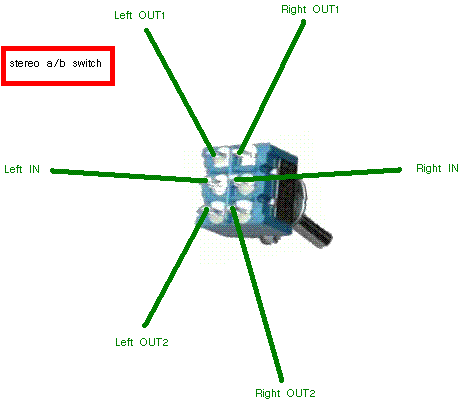
Found the following diagrams at

abstereo.gif


Change the DPDT Toggle to a 3PDT stomper and you've got the third pole to do the LED. Grounds are through the enclosure, I suppose.


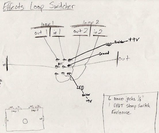
Also from the above thread:

looperpaper.jpg

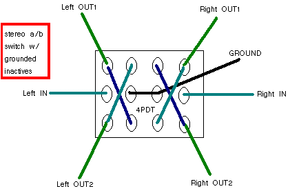
stereoabgrounded.gif
 
it seems like this diagram with the 4PDT is exactly what I’m after. I’m working up a wiring diagram to follow. Which lugs would the LEDs connect to?
The one you selected is better suited to a toggle-4PDT, no LEDs, as ALL lugs are being used for signal routing/grounding.
If you forgo the "grounding while inactive" that would free up the two middle poles, but you only need one pole for LED indication and so you're right back to a 3PDT.


An aside, a nitpick: re the diagram of 4PDT with grounded inactives, I'm curious as to why the ground wasn't sent up the middle of the diagram, there's room for it and it'd be easier on the eyes and brain than having the middle lugs' "ground"-labelling crossing both the Right Out 1 and Right Out 2 pathways.


I would go with the 3PDT and not worry about grounding the inactive signal;
if it 'causes a hum or a problem, only then would I re-think the whole thing.


[EDIT: OOPS! Sure, short the power direct to ground, why not? Thanks to @jwin615 for pointing out the error of my pathways]

STEREO A:B SWITCHER 3PDT.png


Yeesh!
A-B STEREO SWITCHER 3PDT.png
 
Last edited:
I see, thank you. I've never used a bi-color LED. In this scenario, is it on all the time, indicating which output (A or B) is activated? And would the resistor connect to the common anode?
 
So here's what I have so far. Seem OK?

Looking at the above samples it's not clear to me how to connect the bi-color LED. I would also be ok with using 2 different color LEDs also. Can anyone advise me on this? Please and thank you!
 

Attachments

  • Stereo AB wiring copy.png
    Stereo AB wiring copy.png
    122.1 KB · Views: 22
So here's what I have so far. Seem OK?

Looking at the above samples it's not clear to me how to connect the bi-color LED. I would also be ok with using 2 different color LEDs also. Can anyone advise me on this? Please and thank you!
With a common anode bi-color led, the clr would connect to pin 5 and to the LED. then one cathode would connect to pin 4 and the other pin 6.
 
Thanks. It was the mono one early in this thread that confused me. So like this then?
 

Attachments

  • Stereo AB wiring copy.png
    Stereo AB wiring copy.png
    141.5 KB · Views: 30
@joelorigo — the diagram in post #10 is essentially the same as that in post #6, except for the labelling/routing [EDIT: and my horrendous mistake]... I found your tips&sleeves labelling a little confusing.


I figured out what was throwing me off and relabelled some of it (NB tip & sleeve OUT B) [EDIT: needed some more Rx on the diagram, replaced it — mea culpa! ]:


Stereo AB wiring JOELORIGO.png


GREEN = L (TIP)
BLUE = R (SLEEVE)

ONE IN
TWO OUTS, "A" and "B"


Toggle position included in case of using that instead of a stomper.

You could fit it all in a 1590B, depending on jacks selection and their related positions/drilling choices.


And in answer to an earlier query in the thread, the LED would always be on, indicating whichever channel is active.
LED is colour-coded to match the channels — alas, while I've seen green/red, green/blue, blue/red, amber with any of the aforementioned colours ...
... I've never seen purple/amber. Pity.
 
Last edited:
Thanks for the reply here! I ended up not needing this device so I haven't thought about it since these original posts. I am going to have to familiarize myself with what is going on here! Maybe I'll build it and figure out use for it but also, I think this info is good for anyone else looking into this.
 
I can’t get the led to light up when 9v is applied. It will light up dimly when test continuity with any of the dc jack lugs and the center pin of led or any of the center lugs of the 3pdt switch and the center led pin. None of the audio jacks are wired yet.

Help!
IMG_6672.jpeg
 
Last edited:
Thanks for the reply here! I ended up not needing this device so I haven't thought about it since these original posts. I am going to have to familiarize myself with what is going on here! Maybe I'll build it and figure out use for it but also, I think this info is good for anyone else looking into this.
Yeah, I saw post #14 but still felt bad I'd missed the requests made when the thread was fresh.


I can’t get the led to light up when 9v is applied. It will light up dimly when test continuity with any of the dc jack lugs and the center pin of led or any of the center lugs of the 3pdt switch and the center led pin. None of the audio jacks are wired yet.

Help!
View attachment 84461

Have you opened up a trouble-shooting thread? If so, provide the link. If not, start one and provide the link. 😉
I think I see what the problem is...
 
Back
Top