You are using an out of date browser. It may not display this or other websites correctly.
You should upgrade or use an alternative browser.
You should upgrade or use an alternative browser.
Missing Build Docs / Schematics
- Thread starter Robert
- Start date
Nostradoomus
Well-known member
https://forum.pedalpcb.com/threads/pedalpcb-chop-shop-v2.22224/ should workIs there a drill template for the Breakroom or a comparable template that would work?
Robert
Reverse Engineer
Hello, is there a Tayda drill template for the Mofeta Preamp?
The standard 6-knob template should work.
Robert
Reverse Engineer
Hey, I’m in search of the build documents for the Liquid Crystal Fuzz.
Thanks in advance
It's identical to the "Chelsea" variant in the Muffin build docs:
fontoponto
Well-known member
About the Acrobat -> bumpYes, of course. I've been away from my bench for a few days so I have some catching up to do, but I'll get it posted for you.
Same subject but different request: would love just a drill template for the MicroXLR. I’m never too worried about drilling Pots and what not and most of the time the dimensions are similar from pedal to pedal. This XLR gives me anxiety because of the two mounting screws and I’d like to modify some existing pedals so fubar’ing a perfectly good enclosure is another layer of anxiety.
Thanks!
benny_profane
Well-known member
Reference the device datasheet.Same subject but different request: would love just a drill template for the MicroXLR. I’m never too worried about drilling Pots and what not and most of the time the dimensions are similar from pedal to pedal. This XLR gives me anxiety because of the two mounting screws and I’d like to modify some existing pedals so fubar’ing a perfectly good enclosure is another layer of anxiety.
Thanks!
Morbidpale
Active member
Believe me I tried. Im sure it's somewhere obvious.
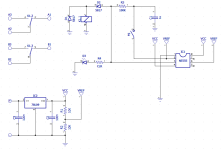
Is there a schematic for the
Basic Relay DPDT switch? Non latching. Im soooo confused trying to figure this out.
Is there a schematic for the
Basic Relay DPDT switch? Non latching. Im soooo confused trying to figure this out.
Robert
Reverse Engineer
Morbidpale
Active member
Much appreciated!
Sounds like a great way for me to fubar a perfectly good enclosure. It’s why I made a request.Reference the device datasheet.
benny_profane
Well-known member
Oh man you’re right what was I thinking.Sounds like a great way for me to fubar a perfectly good enclosure. It’s why I made a request.
Robert
Reverse Engineer
Same subject but different request: would love just a drill template for the MicroXLR.
Try this, double check it before drilling.
@benny_profane is correct though, the drill template could vary depending on the XLR jack used. The attached template is for the XLR jack from Tayda, if you use a different jack you'll need to adjust the coordinates according to the datasheet.
Attachments
Yes, I’m aware that it could change depending on the jack used but in my parts I have 2 other panel mount XLR jacks, that aren’t solder lugs. Besides the part you specified neither fit the footprint of the board. Begs the question of why would anyone use a different jack.Try this, double check it before drilling.
@benny_profane is correct though, the drill template could vary depending on the XLR jack used. The attached template is for the XLR jack from Tayda, if you use a different jack you'll need to adjust the coordinates according to the datasheet.
Messages received loud and clear, Benny. I’ll fuck off now and won’t ask anymore questions. Thanks for creating an inviting place to be.
Robert
Reverse Engineer
Yes, I’m aware that it could change depending on the jack used but in my parts I have 2 other panel mount XLR jacks, that aren’t solder lugs. Besides the part you specified neither fit the footprint of the board. Begs the question of why would anyone use a different jack.
I apologize if my reply came across the wrong way. I attached the template that I used for the jack from Tayda.
As far as why anyone would use a different jack, some folks don't order parts from Tayda Electronics. The jack supplied by Tayda is a knockoff of another brand (most likely Neutrik), and in more cases than not, some dimension might be different compared to the original.
I wasn't sure if I had listed part numbers anywhere yet and would rather warn you than let you mis-drill your enclosure.

