Abyss Rate LED possible?

Sparky_mark

New member
Hi all,
Just finished putting together The Abyss, pretty pleased with it for a phase. A lot of fun after a fuzz also.
Before I start on the enclosure and boxing it up I wanted to find out if its possible to add a rate LED or maybe its too much of a pain in the ass?
It's not the end of the world but maybe someone a lot smarter than me can see if it would work.
Thanks
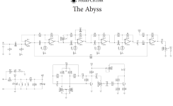
Screenshot 2023-05-28 at 08.20.30.png
 
Hi all,
Just finished putting together The Abyss, pretty pleased with it for a phase. A lot of fun after a fuzz also.
Before I start on the enclosure and boxing it up I wanted to find out if its possible to add a rate LED or maybe its too much of a pain in the ass?
It's not the end of the world but maybe someone a lot smarter than me can see if it would work.
Thanks
View attachment 49405
Was about to ask this same question! I am thinking (theoretically) that you could tie the anode of the LED to one of the LDRs (or even the internal LED anode pad) to get it to blink at the same rate. My intro to circuits class that I took 5 years ago is dull in the brain, but making a new parallel branch shouldn't (?) drop the voltage. The current would drop, but current draw for a LED should be tiny. Wanted to get a sanity check first from those who know better!
 
After looking at the diagram more, it looks like the LDR receive VREF. Which is 9v or less, idk. The LDR go from 10k to 20k, so I tied the anode to the back end of the LDR to check function. Sure, it's dim because I am undervolting the LED by a lot, but still plenty visible since I am using a footswitch LED for this build.
 
Coming back, so this method makes a pretty LED but absolutely DESTROYS the tone. Going to try attaching it to the LED anode instead later and will report back
 
Check around r26?
Maybe split off the emitter of q2 with a 10k (CLR) and led?
I'm guessing q2 is switching D2 for the ldrs. Sorry if this is completely wrong. Not familiar with the EV circuit, just glancing at the schem over lunch.
 
Or maybe better to come off the collector with a clr to ground.
Either way, it will be varied with the intensity knob.
May not be the best solution...
 
I'm going off the bean vibe pcb. He pulled off the emitter of a Darlington pair.
Will probably have to rebalance r26 to keep the gain the same though.
But, if it works it works. Would be opposite cycle, but whatever
 
If you haven't figured anything out yet, could cowboy it...
Probe around with a DMM between r21 and r26 with the rate set slow. Actually, an analog meter may be even better for this, if you have one. Find points of oscillating acceptable voltage and note them. Then just start poking around with the anode of a led with a clr tacked onto it and the cathode tied to ground.
If you have a looper or other musical sound source to feed the pedal, do so.
Find a point that works and doesn't mess with the audio. You won't hurt anything except maybe the led.
 
I know this is an old thread, but in case anyone is still following, I found a YouTube demo where the builder has a pulsing rate LED on his pedal.

Bloomin' Vibe Demo // EQD The Depths Clone


Someone asked in the comments how this was achieved, and the builder replied, "it's quite easy. the effect is internally controlled by an LED ("optical vibe"). So the external LED is actually just a duplication of the internal LED. I connected the legs of the external LED to the legs of the internal one."
Seems as though that would alter the optos brightness since they'd share the same CLR...
 
Seems as though that would alter the optos brightness since they'd share the same CLR...
I was wondering the same thing, so I experimented with some 5mm Yellow LEDs, a CLR and a 9V battery. I found that 2 LEDs in parallel affects the brightness a little, but the difference is hardly noticeable when connecting them in series. I also tried a 5mm Red LED with a 5mm Yellow and had similar results. Also tried different CLR values; 4.7K and 2.2K.

In the Abyss circuit, there's a 10K Pot (Voice control) feeding the LED, so the range of this control might be somewhat impacted by adding a 2nd LED.
 
I know this is an old thread, but in case anyone is still following, I found a YouTube demo where the builder has a pulsing rate LED on his pedal.

Bloomin' Vibe Demo // EQD The Depths Clone


Someone asked in the comments how this was achieved, and the builder replied, "it's quite easy. the effect is internally controlled by an LED ("optical vibe"). So the external LED is actually just a duplication of the internal LED. I connected the legs of the external LED to the legs of the internal one."

Can also just put another LED in series with D2.
 
With the LED already mounted to the PCB is it possible to add the other LED in series still? Or it is two LEDs connected in series with ones anode and the others cathode connected to PCB?
You would need to unsolder 1 of the LED leads from the PCB. Basically, the anode of the 1st LED is soldered to the anode pad on the PCB, then the cathode from the 1st LED is soldered to the anode of the 2nd LED. Finally, you would solder the cathode of the 2nd LED to the cathode pad on the PCB.
 
So I did the rate LED Mod on this and used two LEDs in series and it works good. A 5mm diffused yellow inside and a 3mm diffused red for the rate. Doesn't seem to have any effect on the voice pot or anything else that I can tell. The PCB mania version of this pedal (submarine device) is actually set up perfect for the rate LED Mod. There's an option for a common cathode bi-color LED with a switch but if you just use a regular LED and get rid of the switch it's possible to use the middle switch lug pad for the anode of the rate LED and the right pad for the cathode and it will be in series with the second LED. When using a regular 5mm LED on this PCB there are 3 holes where the bi-color was supposed to go. The cathode goes into the center hole and anode in the right hole. If you want the LED centered better for the photocells put the cathode in the far left hole and solder it in but don't cut the excess. Then insert the excess cathode into the middle hole from the bottom and solder the remaining holes to hold the LED in place.
 
So I did the rate LED Mod on this and used two LEDs in series and it works good. A 5mm diffused yellow inside and a 3mm diffused red for the rate. Doesn't seem to have any effect on the voice pot or anything else that I can tell. The PCB mania version of this pedal (submarine device) is actually set up perfect for the rate LED Mod. There's an option for a common cathode bi-color LED with a switch but if you just use a regular LED and get rid of the switch it's possible to use the middle switch lug pad for the anode of the rate LED and the right pad for the cathode and it will be in series with the second LED. When using a regular 5mm LED on this PCB there are 3 holes where the bi-color was supposed to go. The cathode goes into the center hole and anode in the right hole. If you want the LED centered better for the photocells put the cathode in the far left hole and solder it in but don't cut the excess. Then insert the excess cathode into the middle hole from the bottom and solder the remaining holes to hold the LED in place.
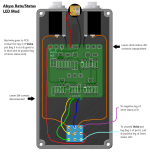
Good to know. Thanks for the update! I just started building my Abyss and I want to do this mod but have the 2nd LED function as both Rate and Status. I came up with a crude drawing for the offboard wiring using a slightly different true bypass wiring scheme. We'll see how it goes.
Abyss Switch Wiring Mod.png
 
Back
Top