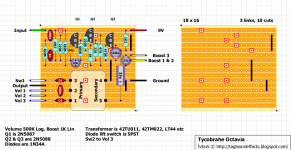
Hi Guys! Long lurker and builder, first post! Maybe someone can help me figure out the wiring, or if its even possible, using SPDT, 3/4PDT, etc as needed. I am wanting to build an Octavia style circuit (already completed) and have the footswitch switch between fuzz (default, octave connection disabled) and octave up (octave connection enabled). Thats easy enough. However I also want to add a switch so that if its engaged, one direction will operate the footswitch as described, but if the switch is flipped I would like the footswitch to act as bypass when flipped. So in the end you either have the ability to enable/disable octave over fuzz, or when switch is flipped, footswitch between the effect and bypass. Thanks in advance, let me know if this makes sense or any questions!
You are using an out of date browser. It may not display this or other websites correctly.
You should upgrade or use an alternative browser.
You should upgrade or use an alternative browser.
Help with switching design
- Thread starter nickbme06
- Start date
I dont have the switch built physically (yet). It would just be a usual 3pdt switch with the bypass wired. Its really irrelevant if what I need in the end has to be started from scratch. But to help understand, the only other function besides usual bypass youd find, is to make a connection in the circuit that would otherwise just be disconnected (this enables/disables octave portion of the fuzz).
Its simple enough to wire footswitch for the bypass fx as usual, and then a flip switch (spdt) that just makes that connection in the circuit that would then enable/disable the octave effect. This just makes it a fuzz fx effectively. The real engineering im trying to see if is even possible with handy wiring is to have the flip switch make it so the footswitch would change duties with the flip switch toggled to enable/disable octave, vs (switch flipped) bypass/fuzz
Its simple enough to wire footswitch for the bypass fx as usual, and then a flip switch (spdt) that just makes that connection in the circuit that would then enable/disable the octave effect. This just makes it a fuzz fx effectively. The real engineering im trying to see if is even possible with handy wiring is to have the flip switch make it so the footswitch would change duties with the flip switch toggled to enable/disable octave, vs (switch flipped) bypass/fuzz
Feral Feline
Well-known member
Maybe an Intelligent Relay Bypass could be made to work?
A quick stomp turns the octave on/off
A long stomp turns the pedal on/off.
or vice versa.
If I understand this correctly, you want JUST fuzz when using the footswitch as bypass.
I think this should work:
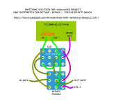
If you want the OCTAVE ON when using the footswitch as bypass, it's easy enough to amend the wiring.
I'm late for work now, so haven't had time to check the diagram.
A quick stomp turns the octave on/off
A long stomp turns the pedal on/off.
or vice versa.
...make it so the footswitch would change duties with the flip switch toggled to enable/disable octave, vs (switch flipped) bypass/fuzz
If I understand this correctly, you want JUST fuzz when using the footswitch as bypass.
I think this should work:

If you want the OCTAVE ON when using the footswitch as bypass, it's easy enough to amend the wiring.
I'm late for work now, so haven't had time to check the diagram.
Hi Feral, Thanks for that!! I haven't looked into using a relay board, that's pretty neat. I can find some uses for that! Not sure it would work as desired for this project. Though your wired diagram with the 4pdt and 3pdt looks like it would do exactly what i was imagining! I'll test a bit today. I'm trying to see now if I can work 2 LEDs in for indications. Thanks so much!!
DailyDovetails
Well-known member
that one took me a few minutes to follow everything through. I wrote it out different but I don’t think I really understood the switch part as I haven’t done any stripboard layoit(they somehow don’t click for me).Maybe an Intelligent Relay Bypass could be made to work?
A quick stomp turns the octave on/off
A long stomp turns the pedal on/off.
or vice versa.
If I understand this correctly, you want JUST fuzz when using the footswitch as bypass.
I think this should work:
View attachment 69855
If you want the OCTAVE ON when using the footswitch as bypass, it's easy enough to amend the wiring.
I'm late for work now, so haven't had time to check the diagram.

I think another LED could be added and then it would read out 4 different states in kind of a binary format of the 4 possibilitys.
DailyDovetails
Well-known member
Something like these could be cool for the status indicators. Could do a different color per status.
Paul.Ruby
Active member
FYI, this is the diode-lift switch to remove Octave. I wanted to see a schematic of it...
 fuzzcentral.ssguitar.com
Looking at the wiring in post 6, this is what it does:
Toggle Down: FS changes between Octave and No octave, Fuzz always on.
Seems to work!
Fuzz Central -- Tycobrahe Octavia
One of the largest sites for do-it-yourself guitar effects builders. Schematics and Printed circuit board layouts for rare pedals like the Tycobrahe Octavia, Clyde McCoy wah and lots of vintage fuzz pedals!
- Both switches up: FUZZ, no Octave.
- FS up Toggle down: FUZZ, With octave.
- FS down Toggle Up: Bypass.
- Both down: FUZZ, no Octave.
Toggle Down: FS changes between Octave and No octave, Fuzz always on.
Seems to work!
Paul.Ruby
Active member
With the bottom switch in the down position, the only option is bypass. The upper switch doesn't matter but shorts input to output in the down position.that one took me a few minutes to follow everything through. I wrote it out different but I don’t think I really understood the switch part as I haven’t done any stripboard layoit(they somehow don’t click for me).
View attachment 69873
I think another LED could be added and then it would read out 4 different states in kind of a binary format of the 4 possibilitys.
Paul.Ruby
Active member
FYI, I have PCB that uses an ATtiny84 to control three latching relays, has 3 inputs (for switches), 2 open collector transistor outputs (for two LEDs) and 3 latching relays. It's for a specific application but is generic enough that it can do this job. It's used in this combo build I posted yesterday:
 forum.pedalpcb.com
Here's a close up of it. Each relay has a spare SPDT that would be used for this. You only need two relays installed. This is obviously overkill for this project... By the way, it says "12VDC" but that is the power input and then the "9VDC" spots are meant to be outputs to other things after the 1N5817 Schottky to protect multiple things inside one pedal.
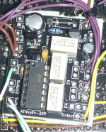
Combo build for pedal board core: Pre-boost, Clean/drive channel, cabsim, noise-gate, post boost.
I've spent an inordinate amount of time creating a combo build with 3 footswitches in a 1590DD case. The picture tells most of the story. I'm happy to share info about it if anyone is interested... I'm wondering if anyone else has any interest in such a thing.... To make this all fit, I had to...

Last edited:
Feral Feline
Well-known member
that one took me a few minutes to follow everything through. I wrote it out different but I don’t think I really understood the switch part as I haven’t done any stripboard layoit(they somehow don’t click for me).
View attachment 69873
I think another LED could be added and then it would read out 4 different states in kind of a binary format of the 4 possibilitys.
Cool! Just got back from work and you've got the LEDs thankfully sorted.
I hear you, re stripboard — I've used vero, sometimes successfully even, but it just doesn't mesh with my brain very well.
...
If anyone has any ideas (maybe using another 4pdt or something) where I can maybe use a multi LED that would be crazy nice.
Changing out the 3PDT-Toggle for a 4PDT toggle for some more LED manipulation may be in order.
I was thinking a bi-colour LED could work well with the circuit, the tri-colour DailyDovetails mentioned would be the bees knees but ... I barely wrapped my brain around getting the wiring-routing on the switches done.
A bi-colour LED, say red/green, could be configured to light green when in FUZZ-ONLY mode/NO LED in BYPASS;
and red when in OCTAVE-OFF mode, and then for OCTAVE-ON mode have both red&green which would give you yellow.
LED — STATUS
OFF = BYPASS
GR = FUZZ-ONLY
- - - - - - - - - - - -
RD = OCTAVE-OFF
YW = OCTAVE-ON
At a glance, you'd be able to tell what you're pedal's doing before you start playing through it.
How to wire it up ... that'll take some more brain-racking.
You could try a blue/green bi-colour LED, which would give you "cyan" as the third colour — but cyan may not be different enough from blue or green under stage lights on a gig.
There are other bi-colour LED colour-combos to test.
Thanks for the suggestions everyone, this is giving great ideas!! I would love to be able to utilize the dual color LEDs if I can figure out wiring with the 2x 4pdt switches. I would have it like this:
LED — STATUS
OFF = BYPASS
GR = FUZZ-ONLY
- - - - - - - - - - - -
YW = OCTAVE-OFF
RD = OCTAVE-ON
LED — STATUS
OFF = BYPASS
GR = FUZZ-ONLY
- - - - - - - - - - - -
YW = OCTAVE-OFF
RD = OCTAVE-ON
DailyDovetails
Well-known member
Thanks for the suggestions everyone, this is giving great ideas!! I would love to be able to utilize the dual color LEDs if I can figure out wiring with the 2x 4pdt switches. I would have it like this:
LED — STATUS
OFF = BYPASS
GR = FUZZ-ONLY
- - - - - - - - - - - -
YW = OCTAVE-OFF
RD = OCTAVE-ON
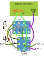
This will give you 4 separate indications with the dual led. You would probably have to mess with where to place the resistors and the colors tho. You might want to put a resistor before each side of the LED to help even the brightness when they are both on.
Sorry Im not following that one, You are just using 1 LED here? Thanks!View attachment 69914
This will give you 4 separate indications with the dual led. You would probably have to mess with where to place the resistors and the colors tho. You might want to put a resistor before each side of the LED to help even the brightness when they are both on.
DailyDovetails
Well-known member
You could use 2 separate LEDs or 1 bicolor which would have 3 legs, ground and one of each color. The drawing is for a single bicolor.
Feral Feline
Well-known member
@nickbme06 — Note that Bi-Colour LEDs come in two different versions:
1) Common Cathode
or
2) Common Anode
Usually the common leg is the one in the middle of the three.
It doesn't matter where you put the CLR, on the anode-path or on the cathode-path, so long as you have the CLR.
Unfortunately, I don't see a way to configure it how you want it, with RED = OCTAVE ON.
Maybe somebody else can work it out another way, but the only way I could configure it is with YELLOW = OCTAVE ON, RED=OCTAVE OFF.
Green always comes on with the stomper, it's the toggle that determines if nothing is added to the stomper's ON position,
When the toggle is switched to OCTAVE MODE, RED is on constantly; engaging the stomper adds the green to red which gives yellow.
I can't see any other way to do it (although maybe there's a way and I'm too fixated on the way I've done it).
I've added a common-cathode BiColour-LED to the diagram and shifted the related poles to the outer edge of the switches for clarity:
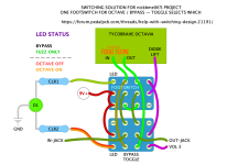
Also note that for the 4PDT-TOGGLE, the way I've depicted it above, when the toggle-bat is up it is the lower part of the switch that is engaged, ie...
TOGGLE UP = FUZZ ALWAYS ON, STOMPER ACTIVATING/DE-ACTIVATING OCTAVE.
TOGGLE DOWN = OCTAVE ALWAYS OFF, STOMPER ENGAGES/BYPASSES FUZZ.

1) Common Cathode
or
2) Common Anode
Usually the common leg is the one in the middle of the three.
It doesn't matter where you put the CLR, on the anode-path or on the cathode-path, so long as you have the CLR.
Unfortunately, I don't see a way to configure it how you want it, with RED = OCTAVE ON.
Maybe somebody else can work it out another way, but the only way I could configure it is with YELLOW = OCTAVE ON, RED=OCTAVE OFF.
Green always comes on with the stomper, it's the toggle that determines if nothing is added to the stomper's ON position,
When the toggle is switched to OCTAVE MODE, RED is on constantly; engaging the stomper adds the green to red which gives yellow.
I can't see any other way to do it (although maybe there's a way and I'm too fixated on the way I've done it).
I've added a common-cathode BiColour-LED to the diagram and shifted the related poles to the outer edge of the switches for clarity:

Also note that for the 4PDT-TOGGLE, the way I've depicted it above, when the toggle-bat is up it is the lower part of the switch that is engaged, ie...
TOGGLE UP = FUZZ ALWAYS ON, STOMPER ACTIVATING/DE-ACTIVATING OCTAVE.
TOGGLE DOWN = OCTAVE ALWAYS OFF, STOMPER ENGAGES/BYPASSES FUZZ.

Similar threads
- Replies
- 24
- Views
- 1K
- Replies
- 9
- Views
- 822


