This is a replica of Schaffer-Vega Diversity System in a pedal from Aion Electronics.
There is no bypass signal. The LED doesn't light up when activated. When the pedal is activated signal passes through - I can verify this because turning the knobs change the sound (the volume make it louder, etc.)
With true bypass in bypass the only circuit is basically input jack -> and wiring -> switch -> wiring -> output jack. You should get a continuous path through all of that. Start at the input end and work through until you find the problem. These switches are pretty heat sensitive, and soldering can certainly damage them if the heat was on a pin for too long. If the switch is dead you pretty much need to either use a dremel or something like that to cut up the switch so you can desolder each pin separately (without damaging the board with either the cutting or too much heat on desoldering) or you need to ditch the board and just use a wired in switch.
With true bypass in bypass the only circuit is basically input jack -> and wiring -> switch -> wiring -> output jack. You should get a continuous path through all of that. Start at the input end and work through until you find the problem. These switches are pretty heat sensitive, and soldering can certainly damage them if the heat was on a pin for too long. If the switch is dead you pretty much need to either use a dremel or something like that to cut up the switch so you can desolder each pin separately (without damaging the board with either the cutting or too much heat on desoldering) or you need to ditch the board and just use a wired in switch.
Hi, as I am pretty new at all this, with no real electronics background, and have never been in this situation, what do you mean by "Start at the input end and work through..." exactly?
The very first thing I'd do is reflow your ground connection on your in jack it looks ball like and could be dry inside if you want to check your grounds go to the end of this novel
I'm not familiar with how Aion wire their 3PDT switches it's not the way I wire mine
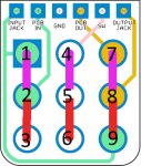
Anyway this is from their micro 3PDT bypass doc so I'd assume this is how all their standard 3PDT boards are wired
2,5 and 8 are the common row which either connects to effects mode (purple lines) where lug 1 input jack would connect to lug 2 pcb in carrying your guitar signal into the effects circuit, lug 5 ground connects to 4 (SW) grounding your LED and switching it on and lug 7 pcb out connects to lug 8 output jack carrying your effected signal to your amp
When clicked or stomped the other way the common row 2,5 and 8 would connect to bypass mode (red lines)
2 pcb in connects to 3 nothing, 5 ground connects to 6 nothing breaking the LED ground connection and switching it off and 9 coming from the input jack connects straight to 8 output jack bypassing the circuit
If all your connections are correct and have good continuity you should get bypassed guitar signal even if your circuit has a fault because it simply connects your input jack straight to your output jack as I say bypassing the circuit and carrying your unaffected clean signal out to your amp
So as PJS says you want to check you have good connections
if you have a meter switch it to continuity mode this symbol below, place your black probe in the COM port and your red probe in the ohms resistance port
I'd check your switch first check to see if your meter beeps from the common row lugs 2,5,8 to the top row lugs 1,4,7 (purple lines) switch it the other way and 2,5,8 should have continuity with 3,6,9 (red lines) then it's a case of checking your other connections have continuity
In bypass mode simply put one probe directly to the in jack tip and the other to the out jack tip, where your yellow and blue wires connect to the jacks
All your connections are labelled so it's easy to check for example your IN on the main pcb has continuity with your PCB in on the 3PDT board and so on, try to put your probes on the solder pads on your 3PDT board rather than the wire ends
A quick way to check all your grounds are good whilst it's in it's enclosure is, in continuity mode stick the black probe in a screw hole and touch all your ground points with the red probe like this, may not work with your painted enclosure if there's paint in the screw holes
In all the above if you get a beep it's got good continuity and therefore has an electrical connection
I'd check your switch first check to see if your meter beeps from the common row lugs 2,5,8 to the top row lugs 1,4,7 (purple lines) switch it the other way and 2,5,8 should have continuity with 3,6,9 (red lines) then it's a case of checking your other connections have continuity
First of all thank you for taking the time to write all that above. That's an excellent description of a lot of things
1 & 2 have continuity, 4 & 5 have continuity and 7 & 8 have continuity. When I switch it the other way 2 & 3 have continuity, 5 & 6 have continuity and 8 & 9 have continuity. However, 1 & 2 have continuity and 2 & 3 both switch positions. So no matter which position the switch is in 1 & 2 & 3 have continuity. Based on the description of how the switch works that doesn't seem right.
In bypass mode simply put one probe directly to the in jack tip and the other to the out jack tip, where your yellow and blue wires connect to the jacks
A quick way to check all your grounds are good whilst it's in it's enclosure is, in continuity mode stick the black probe in a screw hole and touch all your ground points with the red probe like this, may not work with your painted enclosure if there's paint in the screw holes
Paint must not be an issue with this one because when I do it I get continuity on all the pads marked "GND" on the breakout board and both the sleeves on the jacks. Also, since this is the case, it seems that the "ball" solder on the input jack ground is ok, no?
Just to double check what I think is likely to be going on: In bypass mode check the continuity between the jack tips and ground. You are correct that lugs 1,2 and 3 of the switch should not all be connected at the same time. If my reading of the switch connections is correct I think that should result in the signal being grounded in bypass. If that is what is happening you will need to replace the switch. I think if it was me then I would use a new switch without the board. If it comes to that we can help with what to do with the other parts on that board.
In bypass mode, here is continuity between the in and out jack tips. There is continuity between the in and out jack sleeves. There is also continuity between the in tip and in sleeve, between the in tip and out sleeve, between the in sleeve and the out tip. So continuity between all jack points.
I had a situation earlier this year where one of these same switches were a problem. I opened it upon and one of the 3 plates inside the switch was not in the proper position, it was pushed up against the wall. Maybe these are not the best switches.
There should not be any continuity between the jack tips and ground. You can certainly open up the switch and see if there is anything repairable inside. I have done that before and if you have the ability to do that then certainly it can be worth a look. My memory of the construction is that the middle lug should protrude a little higher inside so those plates can only contact one side or the other but not both. If it has fallen a bit you may find you can melt the solder on that one lug and push it through a bit with the iron tip. Be careful and don't have the iron on it for long though - heat is a killer on these switches.
It looks like your switch is faulty albeit rare they can be damaged by too much heat etc and if your switch isn't the best quality it may not take much to damage it internally or you've been unfortunate enough to get a few bad one's
You shouldn't have any continuity at these points
There is also continuity between the in tip and in sleeve, between the in tip and out sleeve, between the in sleeve and the out tip.
So PJS is correct your signal is being pulled to ground
Well, I guess I'll see if I can open up the switch. One advantage of finding something repairable would be the breakout board with the attached parts could be saved.
And does the LED not working when in effects mode fit in with all of this?
Basically repeating what PJS said internets a wee bit slow here tonight we've a storm raging
It shouldn't really affect the LED it's on a different pole 4,5,6 but remember I'm only assuming your breakout board is wired the same as their micro 3PDT board so I'm assuming ground goes to 5 and LED cathode to 4 you could check that your breakout has the same connections as the micro 3PDT e.g does pcb in go to lug 2, ground to 5 etc
I took apart the switch. Nothing looked amiss. I slightly bent the 3 plates as was suggested to me in my troubleshooting thread that the switch was the issue. Still the same result. Looks like the way to go is use a new switch as PJS suggested. But I will definitely need help with that.
If you want to save the breakout board then cut as much off the top of the switch as you can. Then cut 4 cuts in a # shape so that each pin sits by itself. Don't cut down to the board. Then you can desolder each pin individually and remove it. You will need to remove any extra solder and then solder a new switch.
It is probably easier to not save the board. To do that find a wiring diagram for a 3p dt stomp switch. That will show you how to wire the jacks and bypass / engage. The led wiring will be on those diagrams as well. You can solder the resistor directly to the led. I would put some heats rink over the resistor once it is in place to protect and insulate everything. The power supply diode can solder to the power jack. There is a resistor and capacitor that will also need to solder. I would probably do them to the jack assembly as well and insulate it all.
Yes that would work it's the same method I use and ppcb except both ground the input in bypass with the diagonal wire between lugs 1 and 6 to help avoid any switch popping noise