laundryman
Member
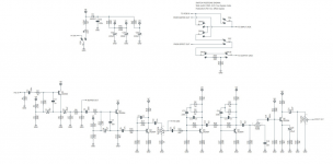
Because of some confusing and conflicting notation on AionFX's PCB, their build docs, and google search, I put the LED in backwards and then totally roasted the pads on both sides trying to get it out. I'm hoping that someone here can take a look at the schematic and find a fix by means of jumping the LED anode and cathode to a couple of other pads. If not, all good. I'm still learning.
(The LED stage is the top left portion of the schematic)


Imgur link to my horrendous attempt
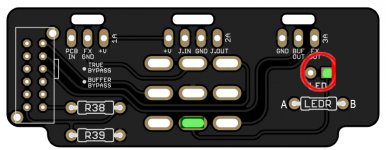
I am able to jumper the LED leads from the 3A and LEDR pads above and below it and light the LED up, but this results in just an always-on state and does trigger with the switch.
If you can make it out in the Imgur photos, the semi-circle symbol at the LED on the PCB points the flat side on the outside. However this is apparently backwards (according to replies I got from a post on diystompboxes forums), and they said the flat side of the LED itself needs to face the inside and lay opposite of the PCB marking. I originally soldered it aligned with the printing on the PCB because I assumed thats how it worked but apparently not.
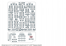
All in all, I'm pretty displeased with Aion FX and plan to stick with only PedalPCB from now on. I know the LED is on me, but the PCB itself is not labeled as the layout is in the image above (I burned off the markings). Aion FX's Help/Support page outright says he isn't going to respond to any customer questions and tells you to ask on an unrelated forum. Everything I found on Google for typical anode/cathode PCB markings was then the opposite again, so I was completely confused. I also found several complaints of this same PCB not having anywhere near the volume that it should, and that the fix is to use Schottky or BAT diodes instead of Germanium, which I changed out and it then worked fine (the build docs call for 5 germanium diodes), so that was a waste of diodes.
I'm not here to gripe, just a forewarning to anyone who happens upon this for their Cygnus build.
Thanks!
(The LED stage is the top left portion of the schematic)


Imgur link to my horrendous attempt
I am able to jumper the LED leads from the 3A and LEDR pads above and below it and light the LED up, but this results in just an always-on state and does trigger with the switch.
If you can make it out in the Imgur photos, the semi-circle symbol at the LED on the PCB points the flat side on the outside. However this is apparently backwards (according to replies I got from a post on diystompboxes forums), and they said the flat side of the LED itself needs to face the inside and lay opposite of the PCB marking. I originally soldered it aligned with the printing on the PCB because I assumed thats how it worked but apparently not.
All in all, I'm pretty displeased with Aion FX and plan to stick with only PedalPCB from now on. I know the LED is on me, but the PCB itself is not labeled as the layout is in the image above (I burned off the markings). Aion FX's Help/Support page outright says he isn't going to respond to any customer questions and tells you to ask on an unrelated forum. Everything I found on Google for typical anode/cathode PCB markings was then the opposite again, so I was completely confused. I also found several complaints of this same PCB not having anywhere near the volume that it should, and that the fix is to use Schottky or BAT diodes instead of Germanium, which I changed out and it then worked fine (the build docs call for 5 germanium diodes), so that was a waste of diodes.
I'm not here to gripe, just a forewarning to anyone who happens upon this for their Cygnus build.
Thanks!
Last edited:


