Ok not sure if im measuring it right but, if i pin the ground to the ground of the lm833 .
Pin 1 keeps jumping around but barely no v
Pin 2 same as number 1
Pin 3 0v
Pin4 0,103v
Pin5 0,102v
Pin6 same as 1
Pin7 sames as 1
If i put ground to the ground of a jack
All the other pins show 0v except pin 3 0.094v and pin 8 0.102
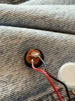
From the picture, it appears your DC socket could be wired wrong. Center negative, sleeve positive. From the pic it appears the red is going to the center pin.
OK. I'll try to give summary of what i've tried so it would be easier for you to understand what i have tried and how to help me.
I checked all the component values. Everything seems to be correct.
I checked the orientation of the caps. And they are correct.
I looked at all of the solders and all of them seem to be ok, even if not all of them that pritty.
The led turns on when pedal is engaged.
When audio probing i get signal until the LM833. I do get a signal from lug 3, and lug 1 gives the faintest little signal that sounds really distorted and awful. After that completely silent.
And the readings i got from the LM833 you can see from earlier comment on this thread.
That's the right way to measure. It does look like your chip is not getting power, and as a matter of fact
nothing may be getting power. +1 to checking the jack wiring and/or the reverse polarity protection diode.
(D1)
Eyeballing the circuit, you should be getting
pin1-3: ~4.5V +/- 1v fluctuation
pin4: 0V
pin5-7: ~4.5 +/- 1v fluctuation
pin8: ~9V
What are the voltages on either side of R8/R9? That is the voltage divider that should be giving you the ~4.5V
that should be showing up on your op-amp(s).
I would expect R8 to show 9V / 4.5V and R9 to show 4.5V / 0V.
I'd measure all the way along your power path:
- At the jack itself
- Either side of D1 (~9V on the left, slightly less on the right)
- C8 (~9V on +, 0V on -)
This is the power section. You mention you've got 8.75V coming out of D1. That's good.
R8 and R9 should be identical on your board. The way the schematic reads you should have approximately 4.5V (a little less in reality) going into pin 5 of IC2. Double check your component values and solder joints here. IC2 is not properly biased.
Have you tried re soldering the joints? I know you said they look fine but you really should solder all parts. Especially the parts buddylereow pointed out.
I have had a badly soldered capacitor stop a pedal from working eve. Though it looked fine
Something is wrong with your IC2. Pins 4 and 8 are ok but you should have around 4.5v going into pin 5 of IC2. If you aren't, then check that R8 and R9 are soldered correctly by reflowing them. You could also have an issue with the IC socket or the IC itself
Finally im hetting sound out of the pedal. Im really not sure what the fix was since i replaced the c8 and both ICs. I also re soldered every part so it was clearly one of those things that worked. Thank you all that helped mi figure this one out))


")