

carlinb17
Well-known member
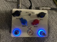
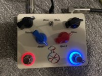
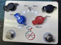
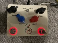
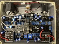
The guts are ugly… I will eventually clean it up. I’m just happy it works! The ring leds were not kind to work with on this build. The clearance for the edge of the pcb to the edge of the foot switch is virtually zero so I had to adapt entire housing. But I got it. The speed switch is red for the red knob and blue for the blue. Bypass is blue on red off. I maybe should have gone with green on but it didn’t match my color scheme.
I thought I ran into an issue because after I housed it and out the knobs on I plugged it in upside down and the light was just solid inside… I took it all apart and tried to figure out why only to eventually realize the intensity knob was turn all the way down when I put the knobs on… all the way down equivalent no modulation….
I thought I ran into an issue because after I housed it and out the knobs on I plugged it in upside down and the light was just solid inside… I took it all apart and tried to figure out why only to eventually realize the intensity knob was turn all the way down when I put the knobs on… all the way down equivalent no modulation….
Attachments
-
 7C0D991E-E6C4-40A4-A3AC-FE2FFBD100E1.jpeg98.7 KB · Views: 53
 -
 12D61851-57FA-496F-A35E-C779B40C6D1A.jpeg94.5 KB · Views: 21
 -
 A2B0BE81-ABE5-44A2-916F-F5AA8C3ABB2A.jpeg85.9 KB · Views: 23
 -
 AD32213F-C558-46CB-86D7-3AE8D86ECB59.jpeg95 KB · Views: 52
 -
 D97EBAEB-20D0-4145-9634-4CC11FA6F932.jpeg153.7 KB · Views: 53