
Thanks. Suspected it wasn’t that simple, but had hoped.No. A balanced signal is phase inverted. It works on the principle that they’ll receive the same interference on both sides of the signal, so when it reaches its end destination, one of the signals is inverted again, maintaining the original signal intact while fully canceling out any interferences introduced along the cable run.
View attachment 51132
Thanks for the heads up. I could just buy a DI box, but where’s the fun in that.If you don't mind their price, there are some balanced line driver ICs that will do a great job with virtually no external components (just power decoupling caps):
THAT1606/1646
DRV134/135
... or you could use an impedance-balanced output, which is the cheapest and easiest of them all to implement. But, you have to know the output impedance of your existing circuit. It has to be fixed, low, and not frequency-dependant (i.e. coming straight from an opamp buffer, not from the wiper of a volume pot). Then you just add a resistor from the "cold" pin of the balanced out connector to ground, with a value matching the impedance from the "hot" (driven) pin to ground. Lots of manufacturers do precisely this, often in lower-priced "balanced out" audio interfaces.Thanks for the heads up. I could just buy a DI box, but where’s the fun in that.
Looks like Mouser has the THAT1646 (wouldn’t think I would need anything more for building a little DI box) for $6. I’ve paid way more for BBDs... or you could use an impedance-balanced output, which is the cheapest and easiest of them all to implement. But, you have to know the output impedance of your existing circuit. It has to be fixed, low, and not frequency-dependant (i.e. coming straight from an opamp buffer, not from the wiper of a volume pot). Then you just add a resistor from the "cold" pin of the balanced out connector to ground, with a value matching the impedance from the "hot" (driven) pin to ground. Lots of manufacturers do precisely this, often in lower-priced "balanced out" audio interfaces.
Vcc and Vee are just the positive and negative supply voltages. For a split rail design, that could be +9 and -9V, referenced to GND. If you’re running a single supply, it’d be +9 and 0V, but you’d also have to provide a (1/2)Vcc reference voltage.Looks like Mouser has the THAT1646 (wouldn’t think I would need anything more for building a little DI box) for $6. I’ve paid way more for BBDs. So looking at the THAT16X6 data sheet it looks like it requires a VCC/VEE supply voltage, how do I accomplish that? I know I’ve seen it in circuits that I have built, I just can’t remember which ones or what IC/components were used?
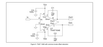
So this is way out of my comfort zone, not necessarily in respect to the terminology but in application. Given this schematic from the data sheetVcc and Vee are just the positive and negative supply voltages. For a split rail design, that could be +9 and -9V, referenced to GND. If you’re running a single supply, it’d be +9 and 0V, but you’d also have to provide a (1/2)Vcc reference voltage.

Offset reduction is not usually necessary. You're going into a balanced input on a mixer or audio interface, which is likely to be AC-coupled anyway, so a few mV of DC offset does not matter.So this is way out of my comfort zone, not necessarily in respect to the terminology but in application. Given this schematic from the data sheet
View attachment 51153
(I chose the offset reduction one simply based on the idea that we typically work to eliminate any DC at the output. Correct me if that is not applicable in this context), using a single 9v supply as is customary for pedal usage, where would Vref (achieved through a voltage divider I presume) and Vee fit?

 groupdiy.com
Thanks! Beginning to think that I should just buy a DI box……..It's probably less work to just generate the missing negative supply with a charge pump.
