SOLVED Broken Distortron troubleshooting

Fama

Well-known member
Hello!

Bypass is fine, very weak signal when active (with drive and volume dimed, not much if they're not at max). I didn't trace the signal the whole way through since I don't have a schematic (apparently it's based on a BOR without the boost so this should be in the ballpark http://3.bp.blogspot.com/-kq989pNrt...V0VA6M2QQ/s1600/zvex_boxofrock_schematics.jpg).

But I did notice while audio probing that I get a good signal loud, nicely distorted signal (with drive and volume dimed) presumably right before Q2, and a very weak signal in Q2, and then a little boosted signal in Q3, so my guess is that Q2 is fried.

Distortron_troubleshooting.png
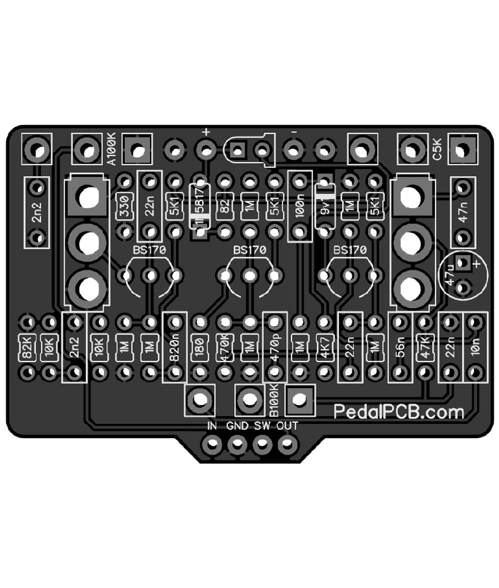
Like I wrote in the image, I get a good signal in the green circles, R12 which seems to lead to C8, and C8 seems to lead to Q2, but the good signal mostly disappears on the other side of C8 (so very weak signal in the blue circles). So that's why I'm wondering whether Q2 is broken.

I also noticed I get a resistance reading from each of the Q2 legs to each other, around 900 to 1.8k ohms or so, that doesn't happen with Q1 or Z1 on the right or Q3. Buuut I can't tell if this is a sign that something is wrong or not for sure, I suspect it might be. I can try measuring voltages, should they be around 4.5V or what?

I'll put in an order for SMT BS170's in the meantime, the only SMT components I have are J201's but they're not a replacement I don't think. Any other ideas I could check out so I could maybe order other parts if it's something else? From my understanding caps and resistors are pretty reliable though, at least compared to BS170's.
 
BS170 are Mosfet
J201 are Jfet.
Did this get plugged into 18 volts, their is a 9.1V zener diode that could have been zapped?
View attachment 56021
I don't know if it has been plugged into a too high voltage, I bought it as broken and the ad didn't mention anything about that. As far as I can see there's just one diode right on the rightmost edge in my picture, marked "YS M7". But there's also a Z1 in addition to Q1-3, so I'm not sure what's up with that. Maybe I'll see if I can order those diodes too just in case.

I'm not good at reading veroboard layouts in the sense of "how the signal is traveling", but D1 seems to be between the source and gate of Q1, so since I presumably get a good signal after Q1, I would guess that's not the issue? Of course it's assuming the signal goes through Q1 before Q2, but I think that's a pretty safe guess.
 
IIRC, static electricity and MOSFETs are not good together. Maybe one (Q2) got zapped?


BTW,
the schematic you posted shows the anode of the zener and the Q1 source going to GAIN-1,
but the vero Music6000 posted shows the zener's anode (and Q1's source) going to GAIN-3.

Begs the question: Which can be trusted, the vero or the schematic?


In your pic: "Q2 third leg nothing (ground?)"
No, according to the schematic you posted none of the Qs go directly to ground; [then I fell asleep and just woke up to new posts from Music6000 and he beat me to the Distortr-punch...] PPCB's Distortr has a switch that takes its Q3-source straight to ground or a resistor to ground (assuming "third leg" was source).

Here's the pinout of a SMD BS170 for reference:
bs170 pinout smd and through-hole.jpeg
Using "Drain" "Gate" and "Source" will be less confusing, as "third leg" could vary depending on if you're going from left to right or top to bottom or some other interpretation of "third leg".


So the pad you circled on Q2 in your pic is the GATE, so I would try to connect the continuity dots and see if the blue circled pad of C8 is the C4 of the schematic you posted (470p, PPCB's C3).

Q3's yellow-circled pad is also the GATE.

I would move forward using Robert's schematic, as he's fastidious about his traces. BTW, Robert's schematic for the Distortr show's the zener's anode as also going to GAIN-3.

I hope my missive helps in some way.
 
IIRC, static electricity and MOSFETs are not good together. Maybe one (Q2) got zapped?


BTW,
the schematic you posted shows the anode of the zener and the Q1 source going to GAIN-1,
but the vero Music6000 posted shows the zener's anode (and Q1's source) going to GAIN-3.

Begs the question: Which can be trusted, the vero or the schematic?


In your pic: "Q2 third leg nothing (ground?)"
No, according to the schematic you posted none of the Qs go directly to ground; [then I fell asleep and just woke up to new posts from Music6000 and he beat me to the Distortr-punch...] PPCB's Distortr has a switch that takes its Q3-source straight to ground or a resistor to ground (assuming "third leg" was source).

Here's the pinout of a SMD BS170 for reference:
View attachment 56022
Using "Drain" "Gate" and "Source" will be less confusing, as "third leg" could vary depending on if you're going from left to right or top to bottom or some other interpretation of "third leg".


So the pad you circled on Q2 in your pic is the GATE, so I would try to connect the continuity dots and see if the blue circled pad of C8 is the C4 of the schematic you posted (470p, PPCB's C3).

Q3's yellow-circled pad is also the GATE.

I would move forward using Robert's schematic, as he's fastidious about his traces. BTW, Robert's schematic for the Distortr show's the zener's anode as also going to GAIN-3.

I hope my missive helps in some way.
Hi or Lo Gain
Q3 Source goes to SPDT to 330 ohm to ground when switched.
Q3 Source goes to SPDT to Ground when switched opposite.
 
Thanks for the tips, I'll do another session probably tomorrow where I'll try to dig in more, I already ordered some BS170's from LCSC because they were dirt cheap, but they will take a while to get here.
 
Thanks for the tips, I'll do another session probably tomorrow where I'll try to dig in more, I already ordered some BS170's from LCSC because they were dirt cheap, but they will take a while to get here.
Be careful when handling, they are sensitive to static electricity
I have never had an issue and don't wear gloves with through hole version but I must be lucky???
I built this way back with my in house eyelet board, it's a versatile distortion box!
Distrort Custom Distortion Pedal 1.jpg
Distrort Custom Distortion Pedal 2.jpg
 
Last edited:
Be careful when handling, they are sensitive to static electricity
I have never had an issue and don't wear gloves with through hole version but I must be lucky???
Rereading the original ad, the poster mentioned they "changed the switch" (probably footswitch), so I'm wondering if the switch was originally faulty and they accidentally touched Q2 and broke it through that... well, it's not important how it happened.
 
Maybe we need to look at the Footswitch wiring also?
No, I checked that and I'm pretty sure it's fine, plus like I mentioned originally, audio probe signal seems fine at R12/C8 but bad after that, and the same signal I probed after Q3 also comes out of the output, so I'm pretty sure the problem is between R12 and Q3.
 
I usually see the ESD protection zener diodes from gate to source, but occasionally you do see them to ground instead.
Looking at the OP’s posted schematic, it’s just the pot that’s flipped around; the zener still goes from Gate to Source like the other versions of the circuit.

I might breadboard the circuit with the zener to ground, see if I hear a difference — thanks for the info.
 
Back
Top