Building a Black Eye : tubes daughter boards mistake, is it really bad ?

eh là bas ma

Well-known member
Hello,

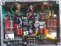
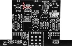
I am building a Black Eye, and unfortunately i made a mistake with the tubes pcb :

I soldered the pins to mount both pcb on the main board, as described in the EZ Tube build doc (pins coming from the side with a circle).
Then i soldered both tube pcbs on the main board, but with the wrong orientation !

I didn't notice the silkscreen on the main board, my pin connectors are pointing toward the opposite direction from the silkscreen.
The tube pcb circles are facing the bottom of the enclosure.

Now I have the sushi box logo pointing toward the jacks, and if i proceed with the tube sockets, they will be soldered on the sushi box logo.
Both tube pcb are slightly closer from the top of the box, instead of being perfectly aligned with the bottom of the main board. But there are still enough room to fit the tubes.

I wonder if this is going to prevent the circuit from working ? Wrong pinouts ?

I am not sure if i'll be able to unsolder the pins, there are 10 of them on each pcb... Is it Game Over for this build ?

If there is some issue with both my tube pcb orientation, is there a way to work around it ? Some way to correct the wrong pinouts, or cut off the connectors ?


Thank you for your help !
 
Last edited:
Sorry to hear about that, it's an unfortunately common mistake. I'm wondering if there's a better way for me to note on the PCB which orientation things should be. If the daughter boards are mounted incorrectly then the pinout will be incorrect and the circuit will not function.
 
Thanks, but even with a desoldering pump, i can't get each pin perfectly cleaned...

I opted for cutting off the pins with pliers, and removing them from the tube board first, then get rid of the connector's remains.

I'll have to build my own 10 pins connectors later...
bummer...

yeah i guess you'll have to keep on pumpin'

or snip them all off and do your best to clean out the holes as you're suggesting.
 
Heat the pad after removing the pins & at the same time pffff with your mouth a burst of air directly over the pad, works for me.
Betty Wont suggests a straw so you don't burn your lips!
Trust me, it works once you get the hang of it.
I often use "impact-assisted solder removal", heat the pad up then whack the board against the bench.
I love it when multiple things I've done in the past that felt sketchy come up as suggested technique.
 
If you dont want to do the straw method an aquarium pump will give you the same result. Just dont melt the silicon tubing to the board, lol. i have an old weller desoldering station and thats essentially whats in it.
 
Thanks for your replies !

I made some progress in my journey.

I manage to mount both tubes on the pcb with the right orientation. Both tubes are slightly lighting up, progressively after activation.

However, the distortion's sound doesn't sound like @MichaelW 's demo...

It's much weaker, creating some beautiful overdrive/distortion sound with Gain fully CW, but with a very dark tone.

Tone control seems to work, i can hear some hi-cut effect going CCW. Even with Tone fully CW, it's better but still muddy and dark.
I need to use a GE-7 and boost everything above 800 kHz : 1.6 K, 3.2 K, and 6.4 K in order to get some interesting sounds. Or i can decrease everything below 1.6K, to "clarify" the sound.

Other controls also are working fine. The box is slightly warm on the sides, when it has been used for a while.

It's just low gain and dark.

I wonder if there is something wrong with my build, or if by any chance it could be related to the choice of tubes ?

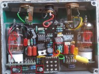
These ECC83 both come from musikding, from a Black Eye kit, and they seeem to work, but I am not sure if they are the correct type ?

IMG_20231130_120340.jpg
IMG_20231130_120355.jpg

It's a high-voltage circuit, so i am not sure how to check with my DMM, if the tubes are getting enough current, for exemple.

Thanks for your help !
 
Last edited:
Thanks for your replies !

I made some progress in my journey.

I manage to mount both tubes on the pcb with the right orientation. Both tubes are slightly lighting up, progressively after activation.

However, the distortion's sound doesn't sound like @MichaelW 's demo...

It's much weaker, creating some beautiful overdrive/distortion sound with Gain fully CW, but with a very dark tone.

Tone control seems to work, i can hear some hi-cut effect going CCW. Even with Tone fully CW, it's better but still muddy and dark.
I need to use a GE-7 and boost everything above 800 kHz : 1.6 K, 3.2 K, and 6.4 K in order to get some interesting sounds. Or i can decrease everything below 1.6K, to "clarify" the sound.

Other controls also are working fine. The box is slightly warm on the sides, when it has been used for a while.

It's just low gain and dark.

I wonder if there is something wrong with my build, or if by any chance it could be related to the choice of tubes ?

These ECC83 both come from musikding, from a Black Eye kit, and they seeem to work, but I am not sure if they are the correct type ?

View attachment 61873
View attachment 61874

It's a high-voltage circuit, so i am not sure how to check with my DMM, if the tubes are getting enough current, for exemple.

Thanks for your help !
I used a 12AU7 in V1 and 12AX7 in V2
 
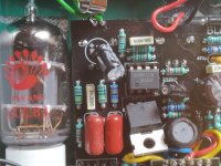
I see a jumble of what looks like stacked resistors, what's going on there? Also it's hard to tell on some of your electrolytics whether they're backwards or if there's just a lot of space between them and the board and they got twisted.

BE EXTREMELY CAREFUL WHEN DEBUGGING HIGH VOLTAGE CIRCUITS. THEY SOUND GOOD, BUT NO TONE IS WORTH DYING FOR.

That being said, how comfortable are you poking it with a multimeter? With these I like to stick the negative lead in one of the enclosure screw holes so it holds itself to chassis ground so I can safely probe positive with just one hand. Probing the DC voltage at the cathode (stripe end) of the UF4007 will tell you what your HV rail is sitting at. If the tubes are heating properly (1700mA OneSpot is plenty) but it still sounds wrong, low voltage on the plates is also possible. You should be seeing something in the 200-240V range.

IMG_20231130_120340.jpg
 
Last edited:
I see a jumble of what looks like stacked resistors, what's going on there? Also it's hard to tell on some of your electrolytics whether they're backwards or if there's just a lot of space between them and the board and they got twisted.
Stacked resistors are 220k + 100k + 10k to get a 330k resistor (missing from the kit).

All electro caps were twisted, but correctly oriented. I left some space between them and the board, so that i can bend them down, if needed.

I took a deep breath and made a voltage reading at UF4007, negative side : I read 170V.

I guess 170V is not enough ?
 
Back
Top