So I toasted my first set of header sockets on my first attempt at the Byzantium (note to self and/or others: don't try soldering the header pins and sockets while they are joined together, unless you want them joined together permanently from solder wicking into the sockets). In the process of removing the ruined sockets, I pulled off some of the PCB pad underneath one of the "inside" headers (the pairs just to the left and right of the resonance trimpot). Good job. 
So now I'm trying to determine whether I've hosed the entire bottom board and now need to start completely over or if it's still redeemable, but I've been unable to determine where in the circuit the header points are (I imagine a full build doc might address that in the future, but I know Robert's not quite there yet – I do have a copy of the Boss BF-2 schemo though, for what it's worth). I did a fairly thorough multimeter beep test, but I got no continuity anywhere on the board on what remains of the pad I bodged. I then tried testing some of the other header points, and I didn't get any continuity for any of the four inside header pads.
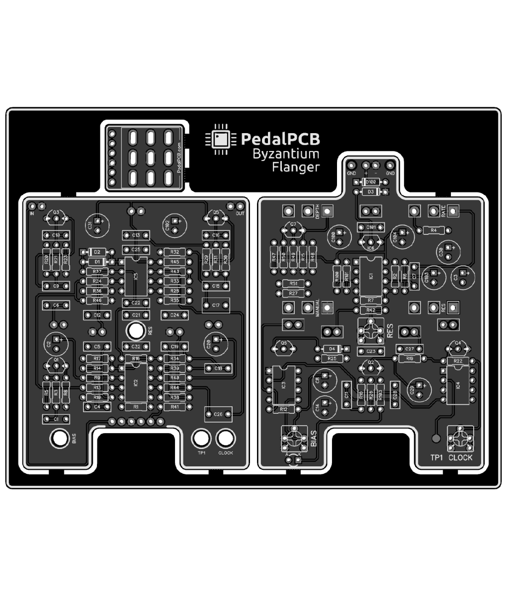
Are these inside headers just there for physical stability, and aren't actually connecting points between the two boards? That would be a very lucky break for me, since I managed to not completely destroy the two outside headers and the one up at the top of the boards (all of which do appear to be connecting necessary points between the boards). If that's the case, then I may be able to salvage it, but I wanted to check with the experts here first before I make any more wild assumptions.
So now I'm trying to determine whether I've hosed the entire bottom board and now need to start completely over or if it's still redeemable, but I've been unable to determine where in the circuit the header points are (I imagine a full build doc might address that in the future, but I know Robert's not quite there yet – I do have a copy of the Boss BF-2 schemo though, for what it's worth). I did a fairly thorough multimeter beep test, but I got no continuity anywhere on the board on what remains of the pad I bodged. I then tried testing some of the other header points, and I didn't get any continuity for any of the four inside header pads.
Are these inside headers just there for physical stability, and aren't actually connecting points between the two boards? That would be a very lucky break for me, since I managed to not completely destroy the two outside headers and the one up at the top of the boards (all of which do appear to be connecting necessary points between the boards). If that's the case, then I may be able to salvage it, but I wanted to check with the experts here first before I make any more wild assumptions.