Chickenhead issue

okstateblues

Active member
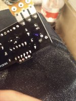
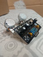
Hello all. I recently built a chicken head treble booster per the BOM but substituted a metal can 2N2222a from digi-key for the CV7112. I have power and sound but with the bias control turned full ccw is the only place I get sound. The sound is also more along the lines of a gated fuzz and I only get sound through the amp if both knobs are dimed along with my guitar volume. Maybe I need to bite the bullet and find the CV7112 as I just built this with the parts I had on hand. Any help is greatly appreciated.
 
check to make sure you have the transistor installed correctly -- the pin out for the 2N222a may be different from the CV7112. for more specific assistance you may need to post detailed pictures of each side of your PCB, along with voltage readings on the legs on the transistor.
 
Yeah it sounds like a bias issue. I have successfully built a Chickenhead with a 2N2222A even though the design calls for a Ge transistor. FWIW it doesn't have to be a CV7112 - I've had great results with Russian MP38 Ge Transistors in this circuit. As far as I can see the pinouts are the same for the CV7112 and 2N2222A.

Maybe try a larger bias pot. Let us know what voltages you are getting at the collector and emitter.
 
I built the Chickenhead in a breadboard earlier today and used a 2N2222 for testing as well. I didn't have any biasing issues. Are you sure both resistors going into the transistor's base are correct? If I recall correctly they should be 470K and 68K.
 
Last edited:
I followed the BOM and didn't deviate. I also ran into another snag trying to remove the bias pot. I pulled the shiny metal "O" from around one of the bias pot legs. Is there any repairing?
 

Attachments

  • IMG_20201021_213411585.jpg
    IMG_20201021_213411585.jpg
    1.3 MB · Views: 10
Just use the schematic to see what it connects to and bypass the trace with a jumper wire

Solder the jumper onto the trimmer leg and to the component it connects to that looks like an outer leg so either goes to ground or C3 + / Q1 emitter

Easy enough to continuity check, if your good one goes to C3 + / Q1 E, then your bad one goes to ground or visa versa

From the pcb image in the shop looks like that one connects to ground so jumper to any ground C3 negative side looks good, the choice is yours!

It's commonly known as hardwiring I usually do it on the underside get a piece of wire tin the ends solder it to the component leg and melt or tack it on to the pad it connects to making sure the ends don't touch or short on anything else

In fact if you look at the image / schematic you may not even need to do that it's wired as a variable resistor and it's attached to the middle lug which already goes to ground just check the middle lug does actually have continuity to ground though! If not get your jumper on!

20201022_130923.jpg
 
Last edited:
Just for info these boards have doubled sided solder pads so if the pad on the other side is ok and still has continuity you can use them, not a great idea with something like a trimmer because of it's depth but with these having board mounted pots it should still fit in ok it will work in reverse ie turn up would be down etc in this case that doesn't matter you're just varying resistance

With things like resistors you just simply place it on the underside and solder on the topside

Once you've fixed the trimmer check Q1 voltages that should let you know if Q1s mis biased I would check that before I'd change anything
 
Back
Top