Arossignol
New member
Hi all, relative newbie here. My first build was the Chop Shop, not realizing I’d have to bias the JFETs and all the complications that brings. I have since built other pedals successfully, and with those under my belt I thought I might be able to troubleshoot the Chop Shop.
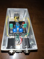
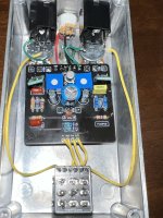
Here’s the deal: after I populated the board I tried biasing the J201s. No luck. With the Sag control all the way CCW (lowest setting) I was getting approx. 9v on both Q1 and Q2 with very little range of control with the trim (.5V both ways). I didn’t have the experience to socket the transistors so I unsoldered both J201s and replaced them. Biased up just fine! Problem solved! Not so fast. After playing it a few days it started acting up. It would barely let any sound through and what did come through was all fizzy. But occasionally it would work fine. Searching the forums I decided maybe I needed to replace the 2N2222 (I only had 2N2222A btw). This time I socketed it. Still no luck. So I changed the J201s (originally used Fairchilds sourced from Smallbear, but this time I tried the SMDs on daughter boards sourced from AionFX.) Still not biasing correctly (correct being 6V). I decided to check every part and lo and behold R7 was the wrong value! It’s connected to Q2 and now I can bias that one just fine. Except Q1 is still not biasing out of the range of about 9.28-9.37V.
I’ve checked the continuity on every connection and everything seems to follow the schematic. I’ve switched the J201s and the one that had biased fine in Q2 won’t bias in Q1 (and vice a versa). I’ve switched out the 2N2222A to no avail. I’m at a loss! I’m hoping you all can see something I’m missing or suggest more troubleshooting ideas.
(Note on the daughter boards: the traces were not right for the pin out on the transistors so I had to improvise crossing the legs lol) Sorry for the long post and thanks for any help!