Colossal Muffin Toggle Issue

VanWhy

Well-known member
I'm having an issue with the toggle switch so I'm looking to get some clarification on the schematic.

Toggle up and Toggle down work fine, center Toggle cuts the signal (aside from some very slight noise). I already tried another switch to eliminate that variable. I'm thinking it may be another component just not sure which.

It's tight to get a audio probe in there so I'm trying to find where to focus on. From what I see on the schematic, toggle 1 position is switching to C2 (100n) and toggle 3 position is switching to C3 (2u2 electro). And according to the PCB trace it looks like toggle 2 is going to R4 (470k). Am I right with that assessment? I swapped out R4 but that didn't help. I can start poking around but no positive where to focus. Any help is appreciated.
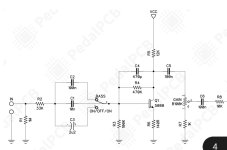
Screenshot_20240902_183155_Adobe Acrobat.jpg
 
according to the PCB trace it looks like toggle 2 is going to R4 (470k)
View attachment 81269
to me it appears toggle pin 2 is going direct to base of Q1.
(R4 is a feedback/biasing resistor for Q1 that would affect all toggle modes).

i’m sure you’ve already done this, but i’d be probing (with toggle in centre position):
- both sides of C1
- base and collector of Q1
- confirm continuity between C1 and Q1 base
 
Last edited:
If you're not getting signal in the middle position it'll have to be the C1 cap. The little bit of noise is just some signal crosstalk from the other traces I'd guess.
So I pulled C1 and it tested fine. Replaced it, and still nothing. I'm stumped.

I also checked and do have continuity from the middle position to the base of Q1. WTF

Edit: Q1 did test fine as well. It was socketed so I pulled the socket and went right in with the transistor to eliminate the possibility of a bad socket. Tested fine and even have continuity still fro. Base to center toggle pad.
 
Last edited:
"So I pulled C1 and it tested fine. Replaced it and still nothing."

You've tested the C1 cap itself and the switch points to the Q1-base... seems you've test all possibilities except...

What I haven't seen, just to clarify, is whether you've tested the PCB at C1b (the switch-side of C1) and heck, for that matter C1a (R2 side...)
— as owlexifry and cdwillis have already mentioned, the problem would seem to be with the C1 location on the board, not the cap itself (for which you've already tested another cap).

Possibles:
Might be a dud board from the manufacturer.
Might be the board got compromised at C1 during initial soldering
Might be ... I have no idea what I'm talking about...


Regardless, post pics!
You know, I have not tested continuity from the C1 pad to the switch and the other side of C1 to R2. I think that's what you mean. I will do that tonight and see. Maybe I will post pics after that. I'm pretty turned off on the whole thing, but I will give it another shot.
 
Back
Top