Conqueror Fuzz, inductor question

Matopotato

Active member
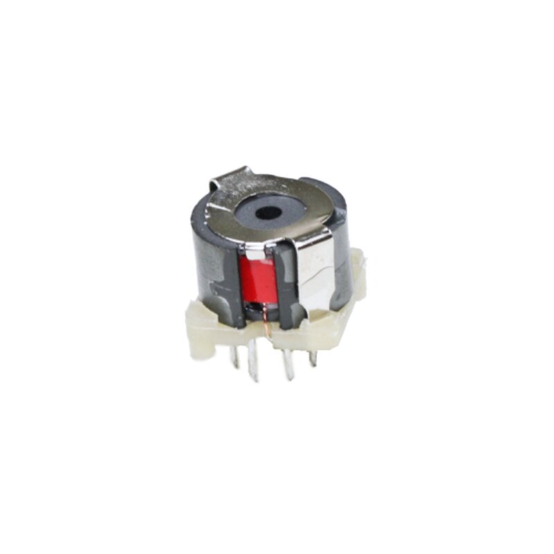
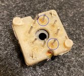
I got an inductor as part of a kit. 8 legs. 2 of them have thin copper wire reaching them, the others seem to not respond to my DMM, but the encircled ones show 730mH (ish) between them.
Which pads on the board should I connect and solder them to?
And should any other legs be soldered to any other pads?
I read somewhere that "put the legs in the holes but do not solder them", which puzzles me.
Thanks in advance.

2022-02-21 20_23_07-20220221_202113.jpg
 
Hello, I'm running into the same problem. Should I soldered only those 2 pins (circled in green by Matopotato) into the holes circled in purple by Chuck D. Bones ? is that correct ? Is there a specific orientation ? Thanks guys :)
 
Show us which transformer / inductor you are using, then we can answer your question.

The general answer is: inductors are heavy and should be restrained to the fullest extent possible. That means soldering ALL leads, inserting & bending tabs, etc. But first, you have to get the orientation right.
 
Looks like the one Matopotato bought. Did it come with a spec sheet? Where did you get it and what is the part number? It looks like Matopotato's, only two leads are used. Make sure those two leads go into the magenta pads, cut off the ones that don't line up with any holes in the board and solder the rest.
 
I am doing another project for a Diamond Compressor clone, and wanted to test out a change of capacitor in one place plus possible spdt. So then I decided to breadboard even if it is a kit with pcb and all.
I think @Chuck D. Bones is a strong proponent for breadboarding anything before soldering. (My ToneVendor MKI adventure...) Even "connect-the-dots" kits.
And it is tedeious. And it is high chance for a guy like me to make shorts in the component forest but:
You really do learn a lot about your project.
And it is much easier to adjust and test and swap stuff when they are not soldered.
A breadboard should be less than 10 Euros, and some "stiff" wire plus buy a few extra phono jacks and dc jack so you can have it in "already started" mode.
I can highly recommend it.
 
I've got one of those. You can see two leads coming from the inductor pins...right beside the half-moon cutouts..here's one;

8dmn3PZ.jpg
 
So if understand you correctly : I should just matter about those 2 pins (wich are connected by a thin copper wire). Insert one in each purple side (circled above by chuck) and that's it ? is there is no specific orientation ? I suppose it shoud line up with the round trace on the pcb ? What about the other pin wich seem to be connected to nothing ? Cut them of ? solder them where I can for support ? thanks guys :)
 

Attachments

  • IMG_8017-pin.jpg
    IMG_8017-pin.jpg
    182 KB · Views: 5
That is how I understood @Chuck D. Bones , but I didn't try myself yet.
All 8 legs will not fit a pad. The two that are key need to. Then the rest either have a pad close, then put it in and solder for extra support. Pins thar do not fit, cut them.
I measured between every pair of pins and all the others came out as "no component" in my multifunc TC-1, a very much cheaper and nit as good as the Atlas above. But sort of ok for my needs.
Can you breadboard before doing the kit?
Also keep me posted how it goes and what you think of it. Excited to know 😁
I don't yet when I will have the time to assemble. Probably in a week. I'll keep you posted. I like to take my time. I remeasure every single component before assembling. And the enclosure is ready (I have the luck to access to a UV printer for free :D )

IMG_8019 2.jpeg
 
That looks to be great!
Haven't done any drilling yet, but plan to stay close to original. Probably no waterslide this time.
 

Attachments

  • 20220225_130657.jpg
    20220225_130657.jpg
    62.6 KB · Views: 3
All finished and it works like a charm ! (and sound awesomely 60iezy by the way ;D)
IMG_8033.jpg

For instructions track :

I did exactly as @Chuck D. Bones said : I solder the two coppered wired leg of the inductor to the top holes
Meaning that I cut all the other leg (they didn't aligned with anything and two leg is plenty strong for support) except the one circled in blue.

IMG_8017-pin.jpg

soldered them in there : (oriented so the inductor kind of match the circle mark) - You don't have much choice to orient it differently anyway.

2022-02-21-20_23_07-20220221_202113.jpg

Hope this recap will help other :) It was a very fun project to do. As always with Pedal PCB !
Musikding provided some weirdly big sized electrolytic caps (I guess there were out of stock of smaller 470uf :D) but with a bit of creativity everything fitted.
 
They provide some weird inductors as well. That footprint doesn't look like any pad pattern I've seen on Cry Baby, Conqueror or anything else. Do you know how much the inductor weighs? Anything over 25g should be spot-glued to the board to relieve stress on the leads and pads.
 
Back
Top