debrad
Active member
At the risk of exposing my electrical ignorance, I just want to check on something that has me a little worried:
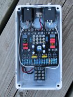
Today I soldered five SMD versions of the MPF4393 (MMBF4393) transistors into my COVERT Overdrive build...something that is relatively new to me. As a check, I measured for continuity between the SMD pads and their associated "thu-hole" pads to make sure the pins were soldered down nicely. I also checked the continuity between the Source and Drain pads, the Source and Gate, and the Drain and Gate to make sure I didn't have any solder bridges.
To my surprise, I appear to have continuity between the Source and Drain pads on all 5 transistors so, after checking the schematic to see if that made sense, I started scouring the web to determine whether this was a sign of damaged parts...I was VERY careful soldering but wouldn't put it past myself to overheat things; however, having said that, I find it hard to believe that I could kill all five!
Anyway, knowing I might not get an accurate reading from transistors soldered into the circuit, I found that each transistor measured between 0.4 and 0.9 V from D-S in "diode mode" as outlined on one site (my DMM indicates ~0.67 V), and approximately 500k from D-S in "resistor mode", but probing the D and S pads together made my DMM beep in "continuity mode". Reading another site, I understand that the resistance between Source and Drain changes depending on whether the transistor is "on" or "off" but I'm just hoping that more knowledgeable folks here in the forum can tell me if what I'm seeing indicates a problem or not.
Thanks!
- brad -
")