Friday Morning Breadboard: FZ-1…

Coda

Well-known member
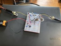
Every Friday morning I like to throw something simple on the breadboard. Today is the Maesteo FZ-1. It needs some tweaking, however. Right now it is very, very clean (like the tone has a crew cut). I’ll post as I fiddle about.

The parts for my protoboard have yet to arrive, so you’ll have to stomach my rig…
 

Attachments

  • 0D435EF7-9620-4AA6-8DFF-72A4B48160FF.jpeg
    0D435EF7-9620-4AA6-8DFF-72A4B48160FF.jpeg
    96.9 KB · Views: 24
Update: I've been working at biasing the transistors. So far I have Q1 (OC140) at -.41 (20k at R3), Q2 (2n2786) at -.62 (470K at R7), and Q3 (2n1605) at .27 (47R at R8 and R9). Q's 1 and 2 are looking good, but I cannot get the voltage of Q3 any higher. I mean, I could, but I don't have any values smaller that 47R...

This is a work in progress. The point of the session is to prep my FZ-1 PCB build. Thanks to the breadboard, I know that some of the Build Doc values will not work for me (Breadboarding saved my life!)...
 
Update: found some time this morning to dig through my stash, and I found an MP21 that measures good for Q3. However, now I’m not getting any signal. So, time to go back and double check things.
 
Did you check the pinouts?

If you look at it from the bottom with the base at TDC, emitter is left, collector right.
 
Nice! I’m gonna breadboard a Sunn buzz soon, which is essentially just a silicon FZ-1A. Are you dropping down to 3v with an LM317 (or other voltage regulator), or a voltage dividing pair of resistors? Can’t make anything out in the picture since my cell service is weak rn
 
Nice! I’m gonna breadboard a Sunn buzz soon, which is essentially just a silicon FZ-1A. Are you dropping down to 3v with an LM317 (or other voltage regulator), or a voltage dividing pair of resistors? Can’t make anything out in the picture since my cell service is weak rn
I am. I replicated the schematic from the Mister Fuzz PCB, since this is a test for that build.
Did you check the pinouts?

If you look at it from the bottom with the base at TDC, emitter is left, collector right.
Pinout is good. I even built an RG Keen tested circuit on another breadboard (I’ve been wanting to for a while). The issue is that as I tweaked, something most like missed it’s hole. I’ll go over it tomorrow.
 
  • Like
Reactions: fig
Yeah, wires pop out, leads touch, these things are fragile. The transistor cases are sometimes hot (electrically), so don't let them touch anything conductive, including each other.
 
  • Like
Reactions: fig
Back
Top